Nissan Almera Tino V10. Manual - part 165
AT-384
[ALL]
BATT/FLUID TEMP SEN (A/T FLUID TEMP SENSOR CIRCUIT AND TCM POW-
ER SOURCE)
Diagnostic Procedure
ECS009BL
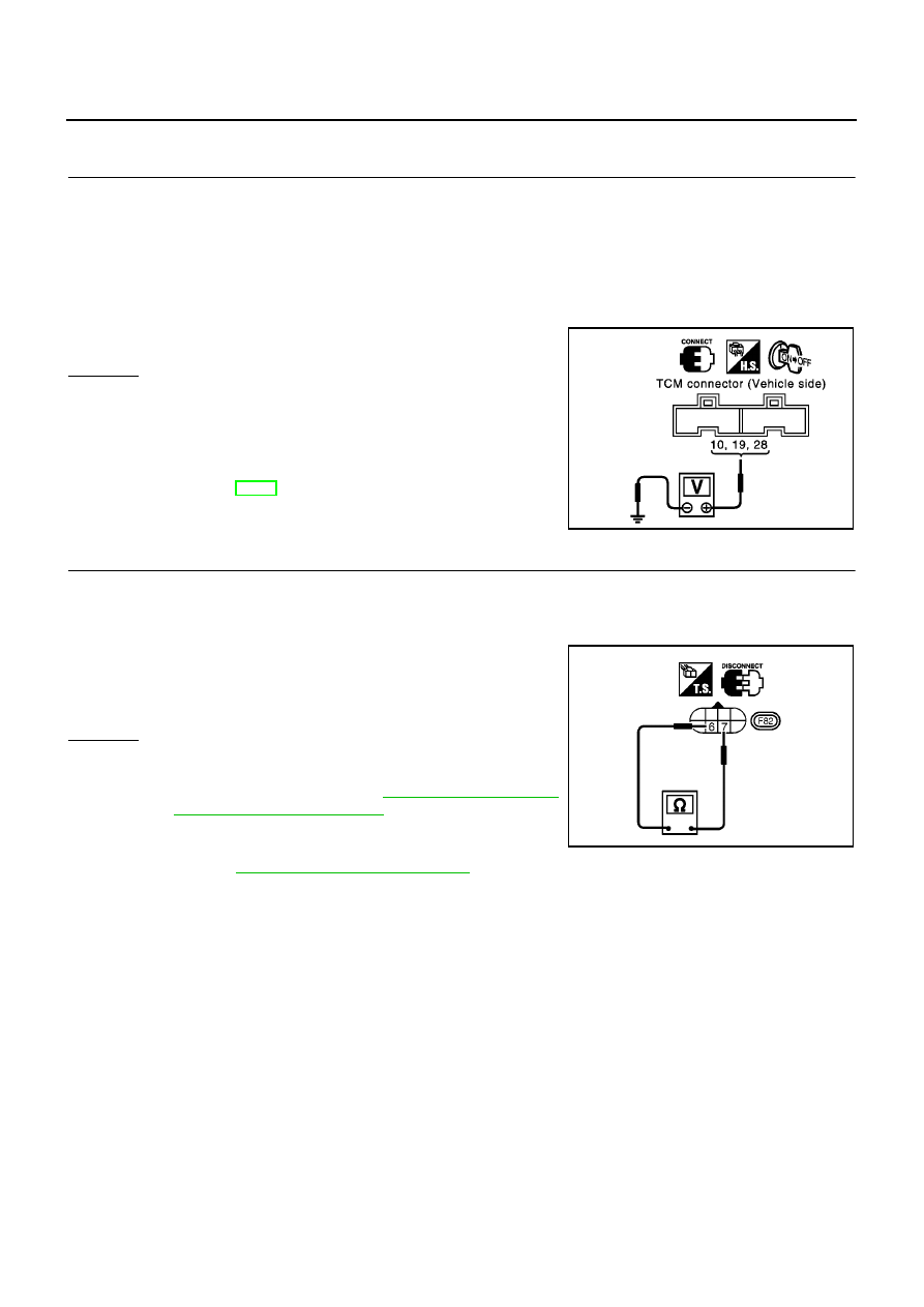
1.
CHECK TCM POWER SOURCE
1.
Turn ignition switch to “ON” position.
(Do not start engine.)
2.
Check voltage between TCM terminals 10, 19, 28 and ground.
3.
Turn ignition switch to “OFF” position.
4.
Check voltage between TCM terminal 28 and ground.
OK or NG
OK
>> GO TO 2
NG
>> Check the following items:
●
Harness for short or open between ignition switch and
TCM (Main harness)
●
Ignition switch and fuse
Refer to EL-11, “Power Supply Routing”.
2.
CHECK A/T FLUID TEMPERATURE SENSOR WITH TERMINAL CORD ASSEMBLY
1.
Turn ignition switch to “OFF” position.
2.
Disconnect terminal cord assembly connector in engine compartment.
3.
Check resistance between terminals 6 and 7 when A/T is cold.
4.
Reinstall any part removed.
OK or NG
OK (With CONSULT-II)>>GO TO 3
OK (Without CONSULT-II)>>GO TO 4
NG
>> 1. Remove oil pan, refer to
.
2. Check the following items:
A/T fluid temperature sensor
Refer to
AT-386, "Component Inspection"
.
Harness of terminal cord assembly for short or open
Voltage: Battery voltage
Voltage: Battery voltage
SCIA0736E
Resistance:
Cold[20
°
C(68
°
F)]
Approximately 2.5 k
Ω
MCIA0101E