Nissan Almera Tino V10. Manual - part 150
AT-324
[EXC.F/EURO-OBD]
TROUBLE DIAGNOSES FOR SYMPTOMS
9. A/T Does Not Shift: D
1
→
D
2
Or Does Not Kick down: D
4
→
D
2
ECS009AF
SYMPTOM:
A/T does not shift from D
1
to D
2
at the specified speed.
A/T does not shift from D
4
to D
2
when depressing accelerator pedal fully at the specified speed.
1.
CHECK SYMPTOM
Are 7. Vehicle Does Not Creep Forward In “D”, “2” Or “1” Position and 8. Vehicle Cannot Be Started From D
1
OK?
Yes or No
Yes
>> GO TO 2
No
>> Go to
AT-320, "7. Vehicle Does Not Creep Forward In “D”, “2” Or “1” Position"
,
.
2.
CHECK PNP SWITCH CIRCUIT
With CONSULT-II
Does “TCM INPUT SIGNALS” in “DATA MONITOR” show damage to PNP switch circuit?
Without CONSULT-II
Does self-diagnosis show damage to PNP switch circuit?
Yes or No
Yes
>> Check PNP switch circuit. Refer to
.
No
>> GO TO 3
3.
CHECK VEHICLE SPEED SENSOR·A/T (REVOLUTION SENSOR) AND CHECK VEHICLE SPEED
SENSOR·MTR CIRCUIT
Check vehicle speed sensor·A/T (revolution sensor) and vehicle speed sensor·MTR circuit. Refer to
"VEHICLE SPEED SENSOR - A/T (REVOLUTION SENSOR)"
and
AT-352, "DTC VEHICLE SPEED SEN-
.
OK or NG
OK
>> GO TO 4
NG
>> Repair or replace vehicle speed sensor·A/T (revolution sensor) and vehicle speed sensor·MTR
circuits.
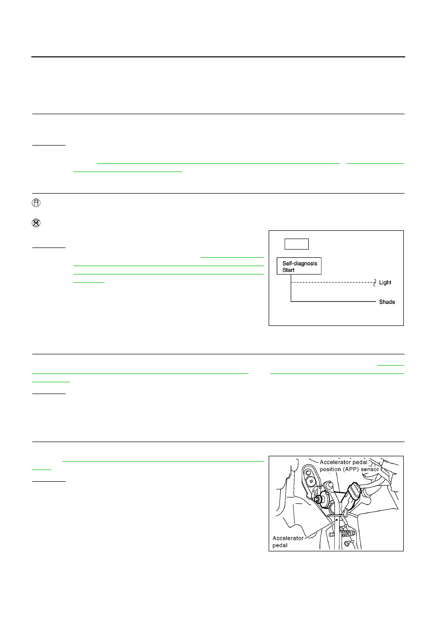
4.
CHECK THROTTLE POSITION SENSOR*
*: This sensor means accelerator pedal position (APP) sensor.
Refer to
AT-356, "ACCELE RATOR PEDAL POSITION (APP) SEN-
.
OK or NG
OK
>> GO TO 5
NG
>> Repair or replace accelerator pedal position (APP) sen-
sor.
SCIA0706E
MCIA0096E