Nissan Almera Tino V10. Manual - part 101
AT-128
[EURO-OBD]
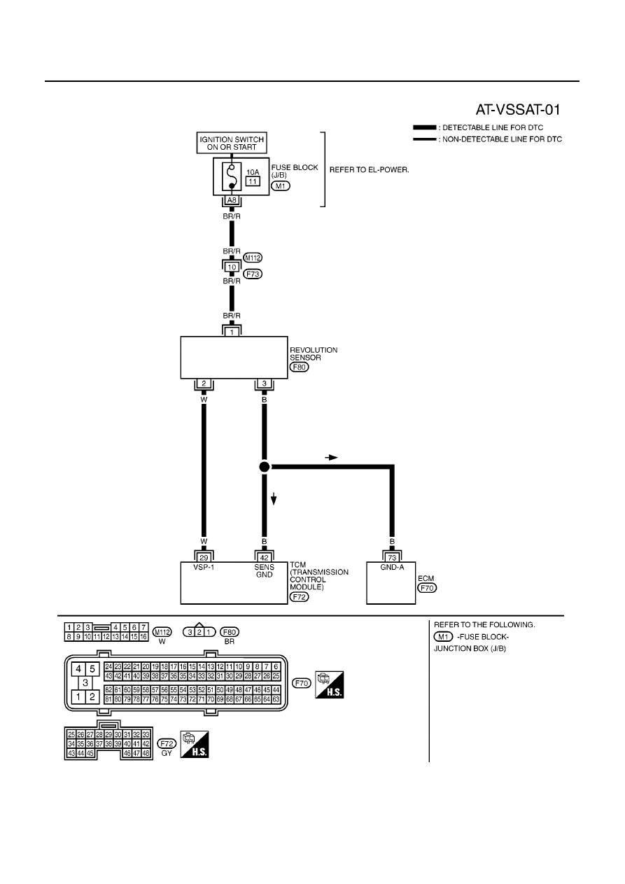
DTC P0720 VEHICLE SPEED SENSOR A/T (REVOLUTION SENSOR)
Wiring Diagram — AT — VSSA/T
ECS0097K
YAT371A
|
|
|
AT-128 [EURO-OBD] DTC P0720 VEHICLE SPEED SENSOR A/T (REVOLUTION SENSOR) Wiring Diagram — AT — VSSA/T ECS0097K YAT371A |