Index Nissan Nissan Almera Tino V10 - Service Manual (2003 year)
Search
Content .. 100 101 102 103 ..
Nissan Almera Tino V10. Manual - part 102
AT-132
[EURO-OBD]
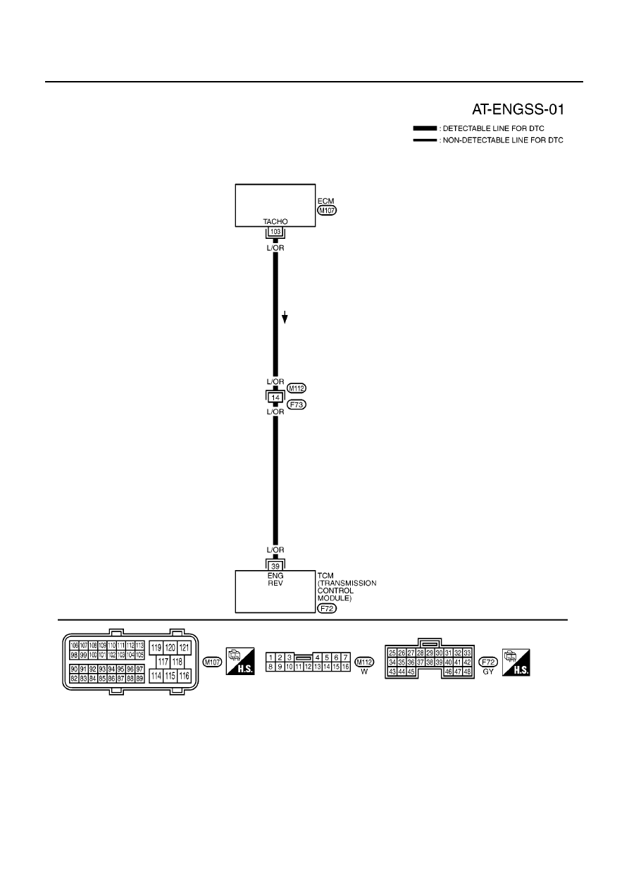
DTC P0725 ENGINE SPEED SIGNAL
Wiring Diagram — AT — ENGSS
ECS0097N
YAT372A