Nissan Almera Tino V10. Manual - part 64
SMA829C
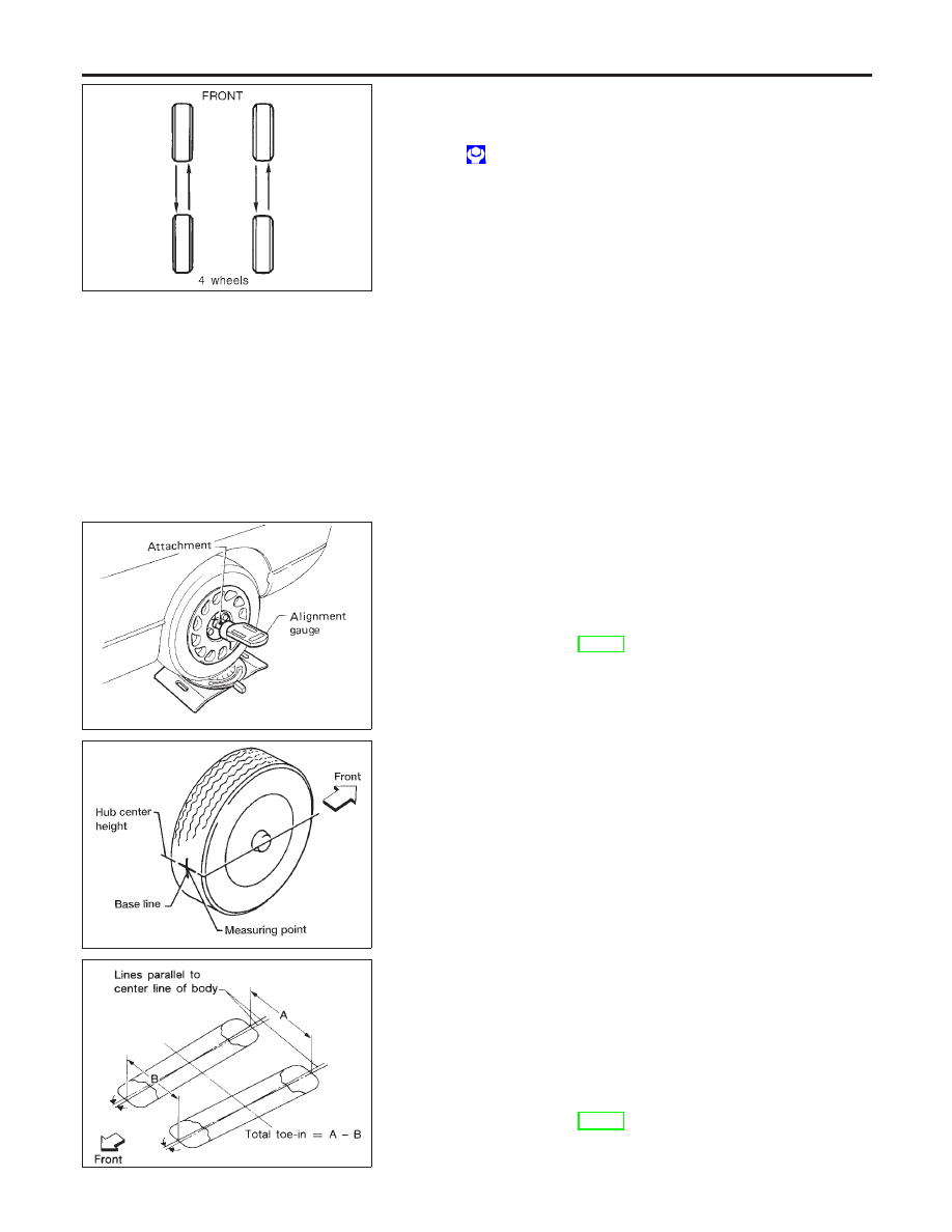
TIRE ROTATION
NLSU0043
I
Do not include the T-type spare tire when rotating the tires.
Wheel nuts:
: 98 - 118 N·m (10.0 - 12.0 kg-m, 72 - 87 ft-lb)
FRONT WHEEL ALIGNMENT
NLSU0045
Before checking front wheel alignment, be sure to make a prelimi-
nary inspection (Unladen*).
*: Fuel, radiator coolant and engine oil full. Spare tire, jack, hand
tools and mats in designated positions.
SRA096A
Camber, Caster and Kingpin Inclination
NLSU0045S01
Camber, caster and kingpin inclination are preset at factory
and cannot be adjusted.
1.
Measure camber, caster and kingpin inclination of both right
and left wheels with a suitable alignment gauge.
Camber, caster and kingpin inclination:
Refer to SDS, SU-15.
2.
If
camber,
caster
or
kingpin
inclination
is
not
within
specification, inspect front suspension parts. Replace dam-
aged or worn out parts.
AFA050
Toe-in
NLSU0045S02
Measure toe-in using the following procedure.
WARNING:
I
Always perform the following procedure on a flat surface.
I
Make sure that no person is in front of the vehicle before
pushing it.
1.
Bounce front of vehicle up and down to stabilize the posture.
2.
Push the vehicle straight ahead about 5 m (16 ft).
3.
Put a mark on base line of tread (rear side) of both tires at the
same height as hub center. These are measuring points.
SFA234AC
4.
Measure distance “A” (rear side).
5.
Push the vehicle slowly ahead to rotate the wheels 180
degrees (1/2 turn).
If the wheels have rotated more than 180 degrees (1/2 turn), try
the above procedure again from the beginning. Never push
vehicle backward.
6.
Measure distance “B” (front side).
Total toe-in:
Refer to SDS, SU-15.
FRONT SUSPENSION
On-vehicle Service (Cont’d)
SU-8