Nissan GT-R. Manual - part 212


  Главная      Nissan     Nissan GT-R (2007-2014 year) - Service Manual


поиск по сайту            


содержание   ..  210  211  212  213   ..


Nissan GT-R. Manual - part 212


MWI

METER SYSTEM

MWI-7

< SYSTEM DESCRIPTION >

C

D

E

F

G

H

I

J

K

L

M

B

A

O

P

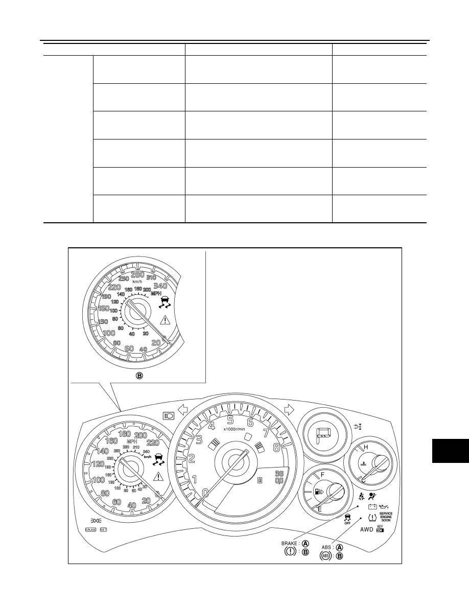
ARRANGEMENT OF COMBINATION METER

Information 
display

Anti-lock braking system 
(ABS) warning display

Based on the received ABS warning display sig-
nal, displays a warning that a malfunction has oc-
curred to ABS.

ABS actuator and electric unit 
(control unit)

Vehicle dynamic control 
(VDC) system warning dis-
play

Based on the received VDC warning display sig-
nal, displays a warning that a malfunction is 
present in VDC.

ABS actuator and electric unit 
(control unit)

Engine system warning dis-
play

Based on the received engine status signal, dis-
plays a warning that a malfunction is present in 
the engine system.

ECM

CRUISE control system warn-
ing display

Based on the received ASCD status signal, de-
tects the CRUISE system malfunction, and dis-
plays a warning that an inspection is necessary.

ECM

Engine oil low pressure warn-
ing display

Based on the received oil pressure sensor signal, 
displays a warning that the engine oil pressure is 
low.

Oil pressure sensor

Low brake fluid warning dis-
play

Based on the received brake fluid level switch sig-
nal, displays a warning that the brake fluid is de-
creased.

Brake fluid level switch

System

Description

Signal source

A.

For U.S.A.

B.

For Canada

JSNIA4767ZZ

MWI-8

< SYSTEM DESCRIPTION >

METER SYSTEM

METER SYSTEM : Component Parts Location

INFOID:0000000009189292

1.

Fuel level sensor unit
(Sub)

2.

Fuel level sensor unit
(Main)

3.

Door switch (passenger side)

4.

Oil pressure sensor

5.

Ambient sensor

6.

Oil level sensor

7.

Washer level switch

8.

AWD control unit

9.

Brake fluid level switch

JPNIA1142ZZ

MWI

METER SYSTEM

MWI-9

< SYSTEM DESCRIPTION >

C

D

E

F

G

H

I

J

K

L

M

B

A

O

P

METER SYSTEM : Component Description

INFOID:0000000009189293

10. ABS actuator and electric unit (con-

trol unit)

11. Door switch (driver side)

12. TCM

13. Trunk switch

14. Combination meter

15. Combination switch (Lighting switch)

16. Low tire pressure warning control unit 17. Parking brake

18. BCM

19. ECM

A.

Under rear seat

B.

Right side of engine

C.

Radiator core support (center)

D.

Oil pan LH upper

E.

Front RH seat under

F.

Trunk room left back

G.

Lower instrument panel LH

H.

Dashboard side lower (passenger 
seat side)

I.

Glove box assembly back

Unit

Description

Combination meter

Based on received signals from each unit, switch, and sensor, controls the following items.

• Speedometer

• Tachometer

• Engine coolant temperature gauge

• Fuel gauge

• Warning lamp

• Indicator lamp

• Information display

Fuel level sensor unit

Detects the fuel level in fuel tank using the fuel level sensor unit, and transmits the fuel gauge sig-
nal to the combination meter.

Oil pressure sensor

Detects the oil pressure of engine oil, and transmits the oil pressure sensor signal to the combi-
nation meter.

ECM

Transmits the following signals to the combination meter via CAN communication.

• Engine speed signal

• Engine coolant temperature signal

• Fuel consumption monitor signal

• Malfunction indicator lamp signal

• Engine status signal

• ASCD status signal

ABS actuator and electric unit 
(control unit)

Transmits the following signals to the combination meter via CAN communication.

• Vehicle speed signal

• ABS warning display signal

• VDC warning display signal

BCM

Transmits signals received from each unit and switch to the combination meter via CAN commu-
nication.

TCM

Transmits the following signals to the combination meter via CAN communication.

• Shift position signal

• Shift lever position warning display signal

• Transmission oil high temperature warning 

display signal

• Transmission clutch high temperature warn-

ing display signal

• Transmission system warning display signal

• Transmission system check display signal

• Shift lever position check display signal

AWD control unit

Transmits the following signals to the combination meter via CAN communication.

• AWD clutch high temperature warning dis-

play signal

• AWD system warning display signal

• Front/rear tire size discrepancy warning dis-

play signal

Low tire pressure warning control 
unit

Transmits the following signals to the combination meter via CAN communication.

• Run-flat tire warning display signal

• Low tire pressure warning display signal

• Tire pressure monitoring system warning dis-

play signal

MWI-10

< SYSTEM DESCRIPTION >

METER SYSTEM

SPEEDOMETER

SPEEDOMETER : System Diagram

INFOID:0000000009189294

SPEEDOMETER : System Description

INFOID:0000000009189295

• ABS actuator and electric unit (control unit) converts the rectangular wave signal from wheel sensor to the

vehicle speed signal, and transmits the signal to the combination meter via CAN communication.

• The combination meter receives the vehicle speed signal from the ABS actuator and electric unit (control

unit) via CAN communication, and indicates the vehicle speed.

Meter control switch

Transmits the following signals to the combination meter.

• Illumination control switch signal (+)

• Illumination control switch signal (-)

• Trip A/B reset switch signal

• Select switch signal

• Enter switch signal

Brake fluid level switch

Transmits the brake fluid level switch signal to the combination meter.

Parking brake switch

Transmits the parking brake switch signal to the combination meter.

Oil level sensor

Transmits the oil level sensor signal to the combination meter.

Washer level switch

Transmits the washer level switch signal to the combination meter.

Ambient sensor

Transmits the ambient sensor signal to the combination meter.

Unit

Description

JPNIA1012GB


содержание   ..  210  211  212  213   ..