содержание .. 208 209 210 211 ..
Nissan GT-R. Manual - part 210
OUTSIDE MIRROR
MIR-17
< REMOVAL AND INSTALLATION >
C
D
E
F
G
H
I
J
K
M
A
B
MIR
N
O
P
4.
Remove mounting bolts, and remove door mirror assembly.
INSTALLATION
Install in the reverse order of removal.
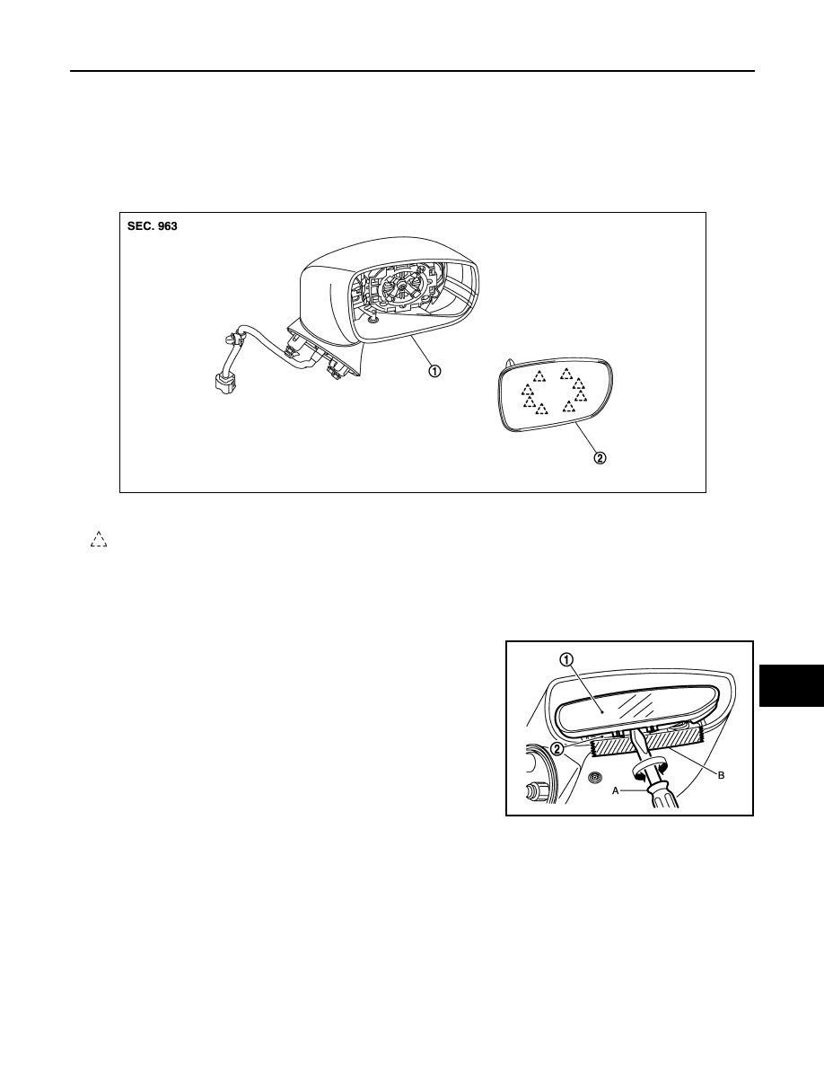
GLASS MIRROR
GLASS MIRROR : Exploded View
INFOID:0000000009159988
GLASS MIRROR : Disassembly and Assembly
INFOID:0000000009159989
DISASSEMBLY
1.
Place the glass mirror upward.
2.
Put a strip of protective tape (B) on housing assembly.
3.
As shown in the figure, insert a small flat-bladed screwdriver (A)
between glass mirror (1) and actuator (2). Push up both pawls
simultaneously to remove glass mirror lower half side.
NOTE:
Insert flat-bladed screwdriver, and push up while rotating (twist-
ing) to make work easier.
4.
Remove two terminals of mirror heater attachment.
5.
Lightly lift up lower side of glass mirror, and detach both pawls of upper side as if pulling it out to disas-
semble glass mirror from actuator.
ASSEMBLY
Assemble in the reverse order of disassembly.
CAUTION:
After installation, check that pawls are securely engaged.
1.
Mirror assembly
2.
Glass mirror
: Pawl
JMLIA0201ZZ
JMLIA0202ZZ