Nissan Pathfinder (2012 year). Manual - part 596
TRANSMISSION ASSEMBLY
TM-195
< UNIT REMOVAL AND INSTALLATION >
C
E
F
G
H
I
J
K
L
M
A
B
TM
N
O
P
UNIT REMOVAL AND INSTALLATION
TRANSMISSION ASSEMBLY
2WD
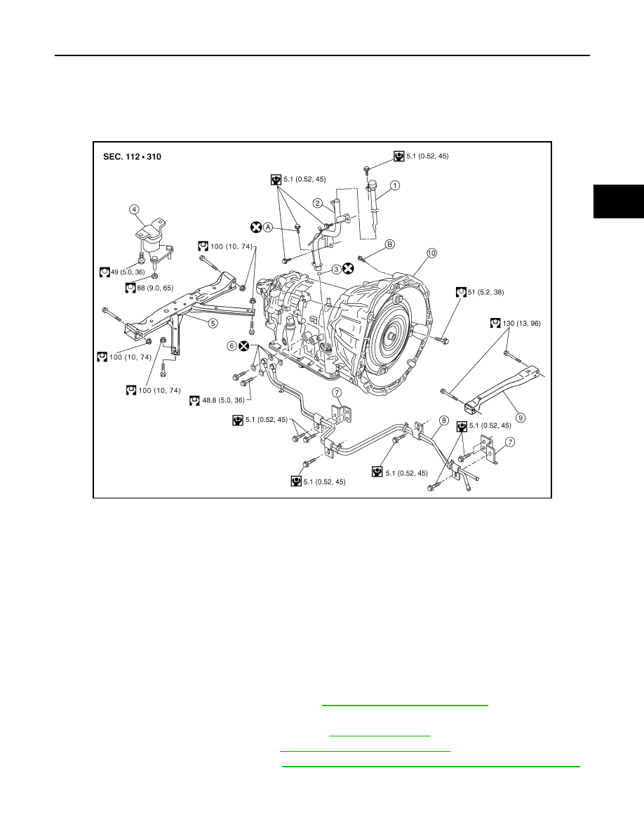
2WD : Exploded View
INFOID:0000000007357313
2WD : Removal and Installation
INFOID:0000000007357314
CAUTION:
When removing the A/T assembly from engine, first remove the crankshaft position sensor (POS) from
the A/T assembly.
NOTE:
When removing components such as hoses, tubes/lines, etc., cap or plug openings to prevent fluid from spill-
ing.
REMOVAL
1. Disconnect the negative battery terminal. Refer to
PG-76, "Removal and Installation"
2. Remove the A/T fluid level gauge.
3. Remove front LH wheel and tire assembly. Refer to
4. Remove the front LH mudguard. Refer to
EXT-26, "Removal and Installation"
5. Remove the LH fender protector. Refer to
EXT-25, "Removal and Installation of Front Fender Protector"
AWDIA0622GB
1.
A/T fluid level gauge
2.
A/T fluid charging pipe
3.
O-ring
4.
Insulator
5.
A/T crossmember
6.
Copper sealing washer
7.
Bracket
8.
A/T fluid cooler tube
9.
Front crossmember
10. Transmission assembly
A. Self-sealing bolt
B. Refer to installation.
August 2012
2012 Pathfinder