Nissan Pathfinder (2010 year). Manual - part 416
FAX-10
< REMOVAL AND INSTALLATION >
WHEEL HUB
WHEEL HUB
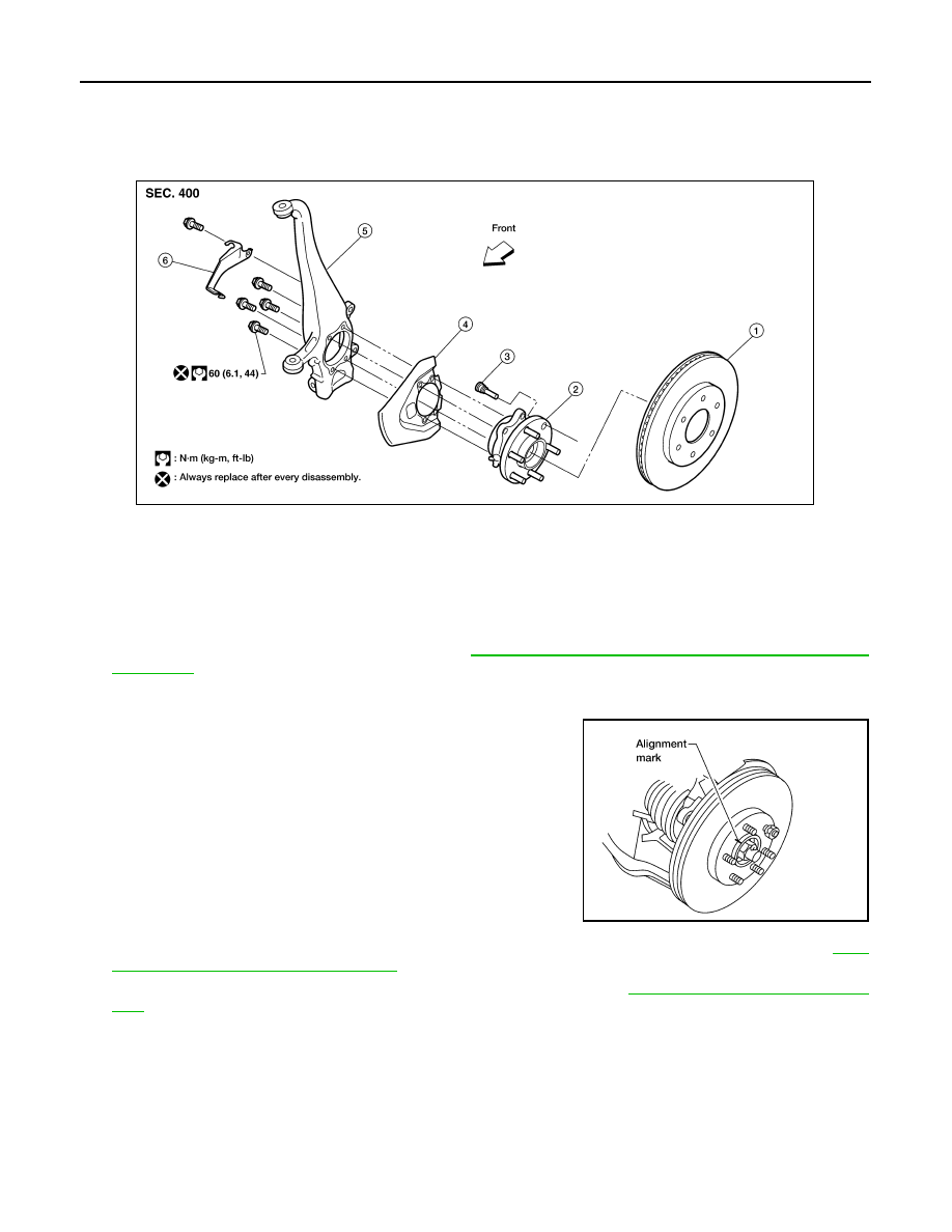
Removal and Installation
INFOID:0000000005255650
REMOVAL
1. Remove wheel and tire using power tool.
2. Without disassembling the hydraulic lines, remove caliper torque member bolts using power tool. Then
reposition brake caliper aside with wire. Refer to
BR-40, "Removal and Installation of Brake Caliper and
CAUTION:
Do not press brake pedal while brake caliper is removed.
3. Put alignment mark on disc rotor and wheel hub and bearing
assembly, then remove disc rotor.
4. On 4WD models, remove cotter pin, then remove lock nut from drive shaft using power tool. Refer to
7, "VQ40DE : Removal and Installation"
.
5. Remove wheel sensor from wheel hub and bearing assembly. Refer to
BRC-125, "Removal and Installa-
• Inspect the wheel sensor O-ring, replace the wheel sensor assembly if damaged.
• Clean the wheel sensor hole and mounting surface with a suitable brake cleaner and clean lint-free
shop rag. Be careful that dirt and debris do not enter the axle bearing area.
• Apply a coat of suitable grease to the wheel sensor O-ring and mounting hole.
CAUTION:
Do not pull on the wheel sensor harness.
6. On 4WD models, separate drive shaft from wheel hub and bearing assembly.
7. Remove wheel hub and bearing assembly bolts using power tool.
8. Remove splash guard and wheel hub and bearing assembly from steering knuckle.
1.
Disc rotor
2.
Wheel hub and bearing assembly
3.
Wheel stud
4.
Splash guard
5.
Steering knuckle
6.
Wheel sensor bracket
WDIA0228E
WDIA0044E
2010 Pathfinder