Nissan Pathfinder (2010 year). Manual - part 414


  Index      Manuals     Nissan Pathfinder (2010 year) - Service and Repair Manual


Search            copyright infringement  


Content      ..     412      413      414      415     ..


Nissan Pathfinder (2010 year). Manual - part 414


LICENSE LAMP FINISHER

EXT-21

< ON-VEHICLE REPAIR >

C

D

E

F

G

H

I

J

L

M

A

B

EXT

N

O

P

LICENSE LAMP FINISHER

Removal and Installation

INFOID:0000000005259118
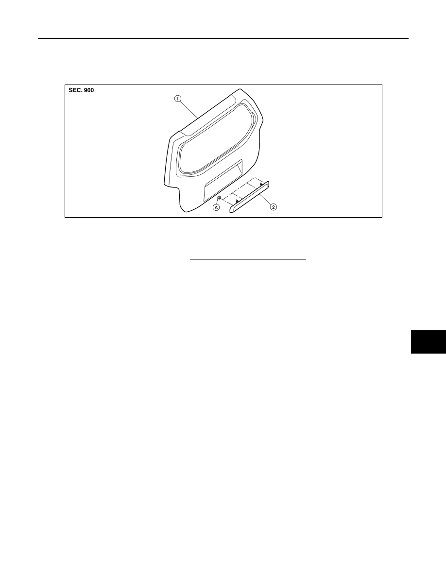
REMOVAL

1. Remove the back door finisher. Refer to 

INT-24, "Removal and Installation"

.

2. Remove the vapor barrier plastic.
3. Remove the license lamp nuts and remove the license lamp finisher.

INSTALLATION

Installation is in the reverse order of removal.

1.

Back door 

2.

License lamp finisher

A.

License lamp finisher nuts

AWKIA0065ZZ

2010 Pathfinder

EXT-22

< ON-VEHICLE REPAIR >

FENDER PROTECTOR

FENDER PROTECTOR

Component

INFOID:0000000005259119

Front Fender Protector

Rear Fender Protector

WIIA1078E

1.

Front fender protector LH shown

2.

Nut

3.

Clip C205

4.

Grommet

Vehicle front

LIIA1764E

1.

Rear fender protector RH

2.

Clips

3.

Nuts

4.

Rear fender protector LH

2010 Pathfinder

FENDER PROTECTOR

EXT-23

< ON-VEHICLE REPAIR >

C

D

E

F

G

H

I

J

L

M

A

B

EXT

N

O

P

Removal and Installation of Front Fender Protector

INFOID:0000000005259120

REMOVAL

1. Remove the front mud flap (if equipped). Refer to 

EXT-24, "Removal and Installation"

.

2. Remove the screws.
3. Remove the plastic clips.
4. Remove the pushpins.
5. Remove the front fender protector.

INSTALLATION

Installation is in the reverse order of removal.

Removal and Installation of Rear Fender Protector

INFOID:0000000005259121

REMOVAL

1. Remove the rear mud flap (if equipped). Refer to 

EXT-24, "Removal and Installation"

.

2. Remove the screws.
3. Remove the plastic clips.
4. Remove the pushpins.
5. Remove the rear fender protector.

INSTALLATION

Installation is in the reverse order of removal.

2010 Pathfinder

EXT-24

< ON-VEHICLE REPAIR >

RUNNING BOARDS

RUNNING BOARDS

Removal and Installation

INFOID:0000000005259122

REMOVAL

1. Remove the mud flaps (if equipped).
2. Remove the bolts and remove the running board from the running board brackets.
3. Remove the nuts and remove the running board brackets from the chassis.
4. Remove the screw and clip and remove the wind deflector.

INSTALLATION

Installation is in the reverse order of removal.

1.

Front mud flap (if equipped)

2.

Running board

3.

Rear wheel wind deflector

4.

Rear mud flap (if equipped)

5.

Running board bracket

LIIA1779E

2010 Pathfinder

ROOF RACK

EXT-25

< ON-VEHICLE REPAIR >

C

D

E

F

G

H

I

J

L

M

A

B

EXT

N

O

P

ROOF RACK

Removal and Installation

INFOID:0000000005259123

REMOVAL

1. Pry outward releasing the clips and remove the slide rail cover front LH and RH.
2. Pry outward releasing the clips and remove the slide rail cover rear LH and RH.
3. Remove the bolts and remove front and rear fixed crossbars, if equipped from slide rails.
4. Remove the bolts from the slide rails LH and RH.
5. Shift the slide rails forward to disengage from the center stanchion and remove.
6. Remove the bolts and remove the center stansions LH and RH. 

INSTALLATION

Installation is in the reverse order of removal.

1.

Slide rail

2.

Fixed crossbar (if equipped)

3.

Slide rail cover rear

4.

Center stanchion

5.

Slide rail cover front

A.

Clip C101

Vehicle front

AWKIA0087GB

2010 Pathfinder

EXT-26

< ON-VEHICLE REPAIR >

DOOR OUTSIDE MOLDING

DOOR OUTSIDE MOLDING

Removal and Installation

INFOID:0000000005259124

DOOR OUTSIDE MOLDING

Removal

1. Lift molding from the front side off of flange.
2. Remove the door outside molding.

Installation

Installation is in the reverse order of removal.

LIIA1780E

2010 Pathfinder

SIDE GUARD MOLDING

EXT-27

< ON-VEHICLE REPAIR >

C

D

E

F

G

H

I

J

L

M

A

B

EXT

N

O

P

SIDE GUARD MOLDING

Removal and Installation

INFOID:0000000005259125

Removal

CAUTION:

Never apply tack-paper adhesive remover to body panel surface finished with lacquer-based paints.

• Original side guard molding is affixed to body panel with double-faced adhesive tape.
1. Heat molding to between 30

°

 and 40

°

C (86

°

 to 104

°

F) with a heat gun.

2. Raise end of molding to release clips, then cut away tape to remove molding. Remove all traces of tape.

Installation

• On vehicles coated with Hard Clear Coat, use double-faced 3M adhesive tape Product No. 4210 or equiva-

lent, after priming with 3M primer Product No. N200 or C-100 or equivalent. 

• The repair parts are also affixed with double-faced adhesive tape.

• To re-use existing molding, clean all traces of double-faced adhesive tape from the molding and apply new

double-faced adhesive tape to the molding.

1. Clean the panel surface with isopropyl alcohol or equivalent to degrease the surface.
2. Heat the panel and molding tape surface to 30

°

 to 40

°

C (86

°

 to 104

°

F).

3. Apply the side guard molding.

• Remove the backing sheet from the tape surface.

• Align the locating pin into the hole in the outer door.

• Continue aligning the pins into their corresponding holes in the outer door during installation.

4. Press ends by hand and use a roller to apply 5 kg-f (11 lbs-f) to press molding to door surface.

• Apply even pressure along molding to insure proper wet out.

CAUTION:

To secure contact, do not wash vehicle for 24 hours after installation.

1.

Alignment hole

2.

Double-faced adhesive tape

3.

Front door side guard molding

4.

Rear door side guard molding

LIIA2724E

2010 Pathfinder

FAX-1

TRANSMISSION & DRIVELINE

C

E

F

G

H

I

J

K

L

M

SECTION 

FAX

A

B

FAX

N

O

P

CONTENTS

FRONT AXLE

PRECAUTION ...............................................

2

PRECAUTIONS ...................................................

2

Precaution for Supplemental Restraint System 
(SRS) "AIR BAG" and "SEAT BELT PRE-TEN-
SIONER" .................................................................
..

2

Precaution .................................................................

2

Precaution Necessary for Steering Wheel Rota-
tion After Battery Disconnect ...................................
..

2

PREPARATION ............................................

4

PREPARATION ...................................................

4

Special Service Tool  .................................................

4

Commercial Service Tool  ..........................................

4

SYMPTOM DIAGNOSIS  ...............................

5

NOISE, VIBRATION, AND HARSHNESS 
(NVH) TROUBLESHOOTING  .............................

5

NVH Troubleshooting Chart  ......................................

5

ON-VEHICLE MAINTENANCE .....................

6

WHEEL HUB  .......................................................

6

On-Vehicle Inspection and Service  ...........................

6

REMOVAL AND INSTALLATION ................

7

DRIVE SHAFT  .....................................................

7

VQ40DE .......................................................................

7

VQ40DE : Removal and Installation ..........................

7

VK56DE .......................................................................

8

VK56DE : Removal and Installation  .........................

8

WHEEL HUB  .....................................................

10

Removal and Installation  .........................................

10

DISASSEMBLY AND ASSEMBLY ..............

12

DRIVE SHAFT ...................................................

12

VQ40DE .....................................................................

12

VQ40DE : Disassembly and Assembly  ...................

12

VK56DE ......................................................................

16

VK56DE : Disassembly and Assembly ....................

17

SERVICE DATA AND SPECIFICATIONS 
(SDS) ............................................................

22

SERVICE DATA AND SPECIFICATIONS 
(SDS) .................................................................

22

VQ40DE .....................................................................

22

VQ40DE : Wheel Bearing ........................................

22

VQ40DE : Drive Shaft ..............................................

22

VQ40DE : Boot Bands .............................................

22

VK56DE ......................................................................

22

VK56DE : Wheel Bearing  ........................................

22

VK56DE : Drive Shaft  ..............................................

23

VK56DE : Boot Bands  .............................................

23

2010 Pathfinder


Content      ..     412      413      414      415     ..