Nissan Pathfinder (2010 year). Manual - part 417


  Index      Manuals     Nissan Pathfinder (2010 year) - Service and Repair Manual


Search            copyright infringement  


Content      ..     415      416      417      418     ..


Nissan Pathfinder (2010 year). Manual - part 417


FAX-18

< DISASSEMBLY AND ASSEMBLY >

DRIVE SHAFT

6. Remove any old grease on the housing using paper towels.

Wheel Side

1. Mount the drive shaft in a vise.

CAUTION:

When mounting the drive shaft in a vise, use copper or aluminum plates between the vise and the

drive shaft.

2. Remove the boot bands, then remove the boot from the joint sub-assembly.
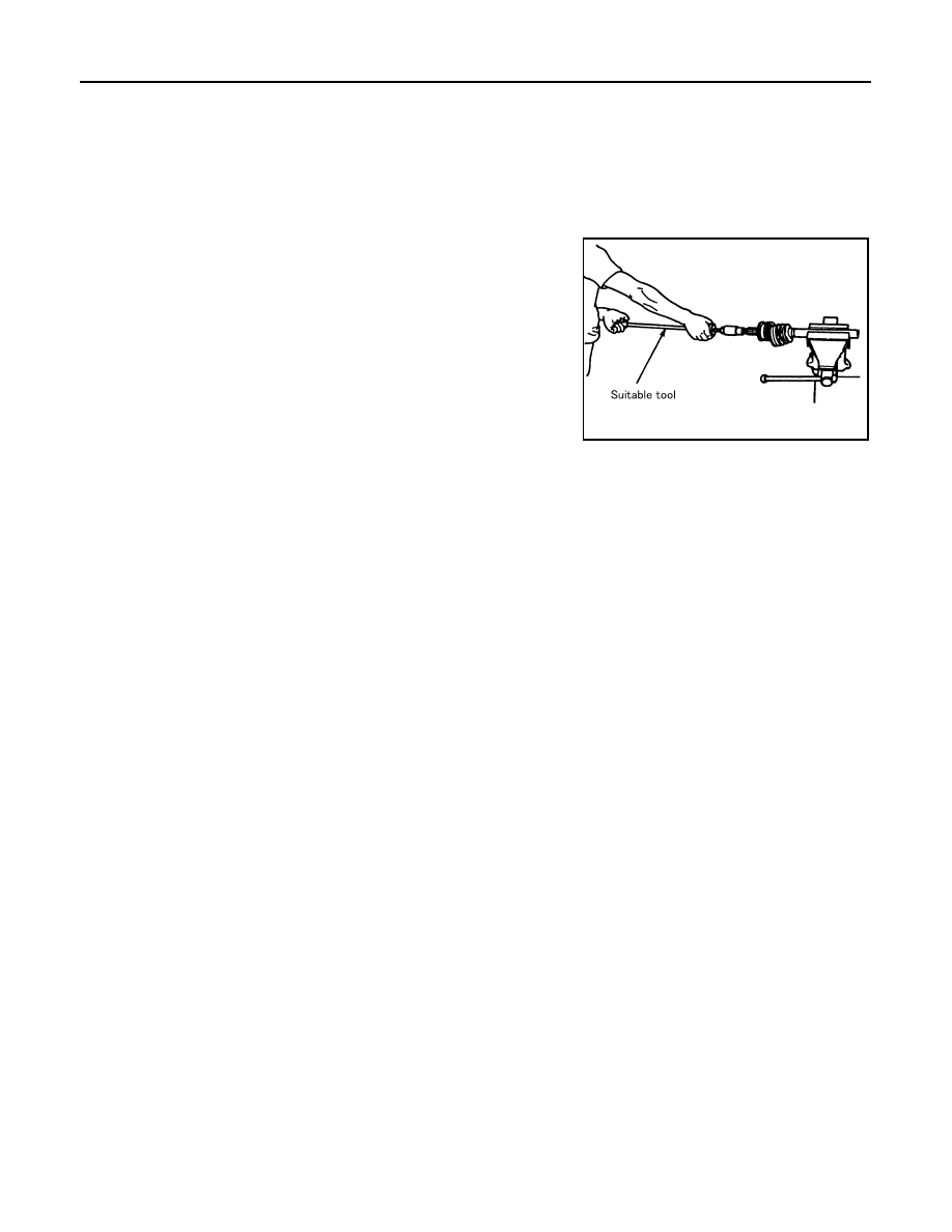
3. Screw a suitable drive shaft puller 30 mm (1.18 in) or more into

the threaded part of the joint sub-assembly. Pull the joint sub-

assembly off of the drive shaft as shown.

NOTE:

Align the sliding hammer and drive shaft and remove the joint

sub-assembly by pulling directly.

CAUTION:

• If the joint sub-assembly cannot be removed after five or

more attempts, replace the drive shaft and joint sub-

assembly as a set.

4. Remove the boot from the drive shaft.
5. Remove the circlip from the drive shaft.
6. While rotating the ball cage, remove any old grease from the joint sub-assembly using paper towels.

INSPECTION AFTER DISASSEMBLY

Drive Shaft

• Replace the drive shaft if there is any runout, cracking, or other damage.

Joint Sub-assembly

• Check for any rough rotation or unusual axial looseness.

• Clean any foreign material from inside the joint sub-assembly.

• Check for any compression scars, cracks, or fractures.

CAUTION:

If any defective conditions are found in the joint sub-assembly components, replace the entire joint

sub-assembly.

Sliding Joint Side Housing

• Check for any compression scars, cracks, fractures, or unusual wear on the ball rolling surface.

• Check for any damage to the drive shaft screws.

• Check for any deformation of the boot installation components.

Ball Cage

• Check the sliding surface for any compression scars, cracks, or fractures.

Steel Ball

• Check for any compression scars, cracks, fractures, or unusual wear.

Inner Race

• Check the ball sliding surface for any compression scars, cracks, or fractures.

• Check for any damage to the serrated part.

CAUTION:

If any defective conditions are found, install a new housing, ball cage, steel ball, and inner race as a

set.

ASSEMBLY

Final Drive Side

SDIA0606E

2010 Pathfinder

DRIVE SHAFT

FAX-19

< DISASSEMBLY AND ASSEMBLY >

C

E

F

G

H

I

J

K

L

M

A

B

FAX

N

O

P

1. Wrap the serrated part of the drive shaft with tape. Install the

boot band and boot to drive shaft.

NOTE:

Discard the old boot band and boot and use a new one for

assembly.

2. Remove the tape wound around the serrated part of the drive shaft.

3. Install the ball cage, steel ball, and inner race assembly on the

drive shaft, and secure them tightly using the snap ring.

NOTE:

Discard the old snap ring and use a new one for assembly.

4. Insert the specified quantity of Genuine NISSAN Grease or

equivalent, onto the housing (indicated by * marks), and install it

onto shaft. Refer to 

MA-16, "For North America"

.

5. Install the stopper ring onto the housing.
6. After installation, pull on the shaft to check engagement between the sliding joint and the stopper ring.

7. Install the boot securely into the grooves (indicated by * marks)

as shown.

CAUTION:

If there is grease on boot mounting surfaces (indicated by *

marks) of shaft and housing, boot may come off. Remove

all grease from surfaces.

8. Check that the boot installation length (L) is the length indicated

below. Insert a flat-tip screwdriver or similar tool into the large

end of the boot. Bleed air from the boot to prevent boot deforma-

tion.

CAUTION:

• The boot may break if the boot installation length is less than the specified value.

SFA800

SDIA1125E

Grease capacity

: Refer to 

FAX-23, "VK56DE : 

Drive Shaft"

.

RAC0678D

Boot installation length (L)

: Refer to 

FAX-23, 

"VK56DE : Drive 
Shaft"

.

WDIA0287E

2010 Pathfinder

FAX-20

< DISASSEMBLY AND ASSEMBLY >

DRIVE SHAFT

• Do not to touch the tip of the screwdriver to the inside of the boot.

9. Secure the large and small ends of the boot with the new boot

bands as shown. 

NOTE:

Discard the old boot bands and use new ones for assembly.

10. After installing the sliding joint housing to the drive shaft, rotate the boot to check that the boot is posi-

tioned correctly. If the boot is not positioned correctly, reposition the boot and secure the boot using a new

boot band.

Wheel Side

1. Insert the Genuine NISSAN Grease or equivalent, into the joint

sub-assembly serration hole until the grease begins to ooze

from the ball groove and serration hole. Refer to 

MA-16, "For

North America"

. After inserting the grease, use a shop cloth to

wipe off the grease that has oozed out.

2. Wrap the serrated part of the drive shaft with tape. Install the

boot band and boot onto the shaft. Do not damage the boot.

NOTE:

Discard the old boot band and boot and use a new one for

assembly.

3. Remove the protective tape wound around the serrated part of

the drive shaft.

4. Attach the circlip to the drive shaft. The circlip must fit securely

into the drive shaft groove. Attach the nut to the joint sub-assem-

bly.

Use a soft hammer to press-fit the circlip.

NOTE:

Discard the old circlip and use a new one for assembly.

5. Insert the specified quantity of Genuine NISSAN Grease or

equivalent, into the joint sub-assembly and the large end of the

boot. Refer to 

MA-16, "For North America"

.

SFA395

SDIA1127E

SFA800

Grease capacity

Refer to 

FAX-23, "VK56DE : 

Drive Shaft"

.

RAC0049D

2010 Pathfinder

DRIVE SHAFT

FAX-21

< DISASSEMBLY AND ASSEMBLY >

C

E

F

G

H

I

J

K

L

M

A

B

FAX

N

O

P

6. Install the boot securely into the grooves (indicated by the *

marks) as shown.

CAUTION:

If there is grease on the boot mounting surfaces (indicated

by the * marks) of the drive shaft and joint sub-assembly,

the boot may come off. Remove all grease from the drive

shaft surfaces. 

7. Check that the boot installation length (L) is the specified length.

Insert a flat-tip screwdriver or similar tool into the large end of

the boot. Bleed the air from the boot to prevent boot deforma-

tion. 

CAUTION:

• The boot may break if the boot installation length is less than the specified length.

• Do not contact inside surface of boot with the tip of the screwdriver.

8. Secure large and small ends of the boot using new boot bands

using tool as shown.

NOTE:

Discard the old boot bands and use new ones for assembly.

• Secure boot band so that dimension (M) meets specification

as shown.

9. After installing the housing to the shaft, rotate the boot to check that it is positioned correctly. If the boot is

not positioned correctly, remove the old boot bands then reposition the boot and secure the boot with new

boot bands.

Boot installation length (L)

: Refer to 

FAX-23, 

"VK56DE : Drive 
Shaft"

.

Tool number : KV40107300 ( — )

WDIA0288E

RAC1133D

Dimension (M)

: Refer to 

FAX-23, "VK56DE : Boot 

Bands"

.

DSF0047D

2010 Pathfinder

FAX-22

< SERVICE DATA AND SPECIFICATIONS (SDS) 

SERVICE DATA AND SPECIFICATIONS (SDS)

SERVICE DATA AND SPECIFICATIONS (SDS)

SERVICE DATA AND SPECIFICATIONS (SDS)

VQ40DE
VQ40DE : Wheel Bearing

INFOID:0000000005255653

VQ40DE : Drive Shaft

INFOID:0000000005255654

VQ40DE : Boot Bands

INFOID:0000000005255655

Unit: mm (in)

VK56DE
VK56DE : Wheel Bearing

INFOID:0000000005255656

Axial end play limit

0.05 mm (0.002 in) or less

Drive shaft joint type

Final drive side

Rzeppa

Wheel side

Rzeppa

Grease

Quality

Genuine NISSAN Grease or equivalent

Capacity

Final drive side

120 - 140 g (4.23 - 4.94 oz)

Wheel side

115 - 135 g (4.01 - 4.76 oz)

Boot installed length (L)

Final drive side

163.9 - 164.3 mm (6.45 - 6.47 in)

Wheel side

135.1 mm (5.32 in)

SDIA2493E

Dimension (M)

1.0 - 4.0 (0.039 - 0.157)

DSF0047D

Wheel bearing axial end play

0.05 mm (0.002 in) or less

2010 Pathfinder

SERVICE DATA AND SPECIFICATIONS (SDS)

FAX-23

< SERVICE DATA AND SPECIFICATIONS (SDS) 

C

E

F

G

H

I

J

K

L

M

A

B

FAX

N

O

P

VK56DE : Drive Shaft

INFOID:0000000005255657

VK56DE : Boot Bands

INFOID:0000000005255658

Unit: mm (in)

Drive shaft joint type

Final drive side

Rzeppa

Wheel side

Rzeppa

Grease

Quality

Nissan Genuine Grease or 

equivalent

Capacity  

Final drive side

110 - 130 g (3.88 - 4.59 oz)

Wheel side

130 - 150 g (4.59 - 5.29 oz)

Boot length  

Final drive side (L)

145 mm (5.71 in)

Wheel side (L)

135.1 mm (5.32 in)

WDIA0055E

Dimension (M)

1.0 - 4.0 (0.039 - 0.157)

DSF0047D

2010 Pathfinder

FL-1

ENGINE

C

D

E

F

G

H

I

J

K

L

M

SECTION 

FL

A

FL

N

O

P

CONTENTS

FUEL SYSTEM

PRECAUTION ...............................................

2

PRECAUTIONS ...................................................

2

Precaution for Supplemental Restraint System 
(SRS) "AIR BAG" and "SEAT BELT PRE-TEN-
SIONER" .................................................................
..

2

Precaution Necessary for Steering Wheel Rota-
tion After Battery Disconnect ...................................
..

2

General Precaution  ...................................................

3

PREPARATION ............................................

4

PREPARATION ...................................................

4

Special Service Tool  .................................................

4

Commercial Service Tool  ..........................................

4

ON-VEHICLE MAINTENANCE .....................

5

FUEL SYSTEM ....................................................

5

Checking Fuel Line  ...................................................

5

ON-VEHICLE REPAIR ..................................

6

FUEL TANK  .......................................................

6

Removal and Installation  ..........................................

6

FUEL LEVEL SENSOR UNIT, FUEL FILTER 
AND FUEL PUMP ASSEMBLY  ........................

11

Removal and Installation  .........................................

11

DISASSEMBLY AND ASSEMBLY ..............

16

FUEL LEVEL SENSOR UNIT, FUEL FILTER 
AND FUEL PUMP ASSEMBLY  ........................

16

Disassembly and Assembly .....................................

16

SERVICE DATA AND SPECIFICATIONS 
(SDS) ............................................................

17

SERVICE DATA AND SPECIFICATIONS 
(SDS) .................................................................

17

Standard and Limit  ..................................................

17

2010 Pathfinder

FL-2

< PRECAUTION >

PRECAUTIONS

PRECAUTION

PRECAUTIONS

Precaution for Supplemental Restraint System (SRS) "AIR BAG" and "SEAT BELT 
PRE-TENSIONER"

INFOID:0000000005510400

The Supplemental Restraint System such as “AIR BAG” and “SEAT BELT PRE-TENSIONER”, used along

with a front seat belt, helps to reduce the risk or severity of injury to the driver and front passenger for certain

types of collision. This system includes seat belt switch inputs and dual stage front air bag modules. The SRS

system uses the seat belt switches to determine the front air bag deployment, and may only deploy one front

air bag, depending on the severity of a collision and whether the front occupants are belted or unbelted.

Information necessary to service the system safely is included in the SR and SB section of this Service Man-

ual.

WARNING:

• To avoid rendering the SRS inoperative, which could increase the risk of personal injury or death in

the event of a collision which would result in air bag inflation, all maintenance must be performed by

an authorized NISSAN/INFINITI dealer.

• Improper maintenance, including incorrect removal and installation of the SRS, can lead to personal

injury caused by unintentional activation of the system. For removal of Spiral Cable and Air Bag

Module, see the SR section.

• Do not use electrical test equipment on any circuit related to the SRS unless instructed to in this

Service Manual. SRS wiring harnesses can be identified by yellow and/or orange harnesses or har-

ness connectors.

PRECAUTIONS WHEN USING POWER TOOLS (AIR OR ELECTRIC) AND HAMMERS

WARNING:

• When working near the Airbag Diagnosis Sensor Unit or other Airbag System sensors with the Igni-

tion ON or engine running, DO NOT use air or electric power tools or strike near the sensor(s) with a

hammer. Heavy vibration could activate the sensor(s) and deploy the air bag(s), possibly causing

serious injury.

• When using air or electric power tools or hammers, always switch the Ignition OFF, disconnect the

battery, and wait at least 3 minutes before performing any service.

Precaution Necessary for Steering Wheel Rotation After Battery Disconnect

INFOID:0000000005255633

NOTE:

• This Procedure is applied only to models with Intelligent Key system and NATS (NISSAN ANTI-THEFT SYS-

TEM).

• Remove and install all control units after disconnecting both battery cables with the ignition knob in the

LOCK

 position.

• Always use CONSULT-III to perform self-diagnosis as a part of each function inspection after finishing work.

If DTC is detected, perform trouble diagnosis according to self-diagnostic results.

For models equipped with the Intelligent Key system and NATS, an electrically controlled steering lock mech-

anism is adopted on the key cylinder.

For this reason, if the battery is disconnected or if the battery is discharged, the steering wheel will lock and

steering wheel rotation will become impossible.

If steering wheel rotation is required when battery power is interrupted, follow the procedure below before

starting the repair operation.

OPERATION PROCEDURE

1. Connect both battery cables.

NOTE:

Supply power using jumper cables if battery is discharged.

2. Use the Intelligent Key or mechanical key to turn the ignition switch to the 

ACC

 position. At this time, the

steering lock will be released.

3. Disconnect both battery cables. The steering lock will remain released and the steering wheel can be

rotated.

4. Perform the necessary repair operation.

2010 Pathfinder


Content      ..     415      416      417      418     ..