Nissan Pathfinder (2010 year). Manual - part 343
EC-836
< COMPONENT DIAGNOSIS >
[VK56DE]
P2100, P2103 THROTTLE CONTROL MOTOR RELAY
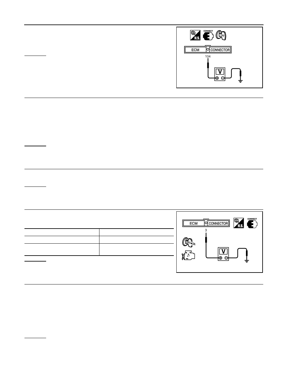
2. Check voltage between ECM terminal 104 and ground with
CONSULT-III or tester.
OK or NG
OK
>> GO TO 4.
NG
>> GO TO 2.
2.
CHECK THROTTLE CONTROL MOTOR RELAY POWER SUPPLY CIRCUIT-II
1. Disconnect ECM harness connector.
2. Disconnect IPDM E/R harness connector E122.
3. Check continuity between ECM terminal 104 and IPDM E/R terminal 47.
Refer to Wiring Diagram.
4. Also check harness for short to ground and short to power.
OK or NG
OK
>> GO TO 3.
NG
>> Repair open circuit or short to ground or short to power in harness or connectors.
3.
CHECK FUSE
1. Disconnect 20A fuse (No. 52).
2. Check 20 A fuse for blown.
OK or NG
OK
>> GO TO 7.
NG
>> Replace 20 A fuse.
4.
CHECK THROTTLE CONTROL MOTOR RELAY INPUT SIGNAL CIRCUIT-I
Check voltage between ECM terminal 3 and ground under the fol-
lowing conditions with CONSULT-III or tester.
OK or NG
OK
>> GO TO 7.
NG
>> GO TO 5.
5.
CHECK THROTTLE CONTROL MOTOR RELAY INPUT SIGNAL CIRCUIT-II
1. Turn ignition switch OFF.
2. Disconnect ECM harness connector.
3. Disconnect IPDM E/R harness connector E119.
4. Check continuity between ECM terminal 3 and IPDM E/R terminal 6.
Refer to Wiring Diagram.
5. Also check harness for short to ground and short to power.
OK or NG
OK
>> GO TO 7.
NG
>> GO TO 6.
Voltage: Battery voltage
PBIB1171E
Continuity should exist.
Ignition switch
Voltage
OFF
Approximately 0 V
ON
Battery voltage
(11 - 14 V)
MBIB0028E
Continuity should exist.
2010 Pathfinder