Nissan Pathfinder (2010 year). Manual - part 341


  Index      Manuals     Nissan Pathfinder (2010 year) - Service and Repair Manual


Search            copyright infringement  


Content      ..     339      340      341      342     ..


Nissan Pathfinder (2010 year). Manual - part 341


EC-820

< COMPONENT DIAGNOSIS >

[VK56DE]

P1554 BATTERY CURRENT SENSOR

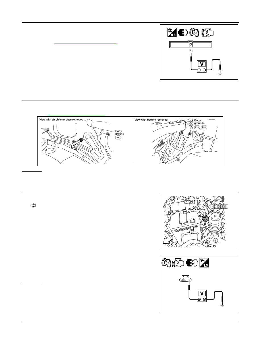
2. Check voltage between ECM terminal 71 (battery current sensor

signal) and ground for 10 seconds.

The voltage should be above 2.3 V at least once.

3. If NG, go to 

EC-820, "Diagnosis Procedure"

.

Diagnosis Procedure

INFOID:0000000005257824

1.

CHECK GROUND CONNECTIONS

1. Turn ignition switch OFF.

2. Loosen and retighten ground screws on the body. 

Refer to 

EC-577, "Ground Inspection"

.

OK or NG

OK

>> GO TO 2.

NG

>> Repair or replace ground connections.

2.

CHECK BATTERY CURRENT SENSOR POWER SUPPLY CIRCUIT

1. Disconnect battery current sensor (1) harness connector.

2. Turn ignition switch ON.

: Vehicle front

3. Check voltage between battery current sensor terminal 1 and

ground with CONSULT-III or tester.

OK or NG

OK

>> GO TO 4.

NG

>> GO TO 3.

3.

DETECT MALFUNCTIONING PART

PBIB2616E

BBIA0539E

ALBIA0362ZZ

Voltage: Approximately 5 V

PBIA9891J

2010 Pathfinder

P1554 BATTERY CURRENT SENSOR

EC-821

< COMPONENT DIAGNOSIS >

[VK56DE]

C

D

E

F

G

H

I

J

K

L

M

A

EC

N

P

O

Check the following.

• Harness connectors E5, F14

• Harness for open or short between battery current sensor and ECM

>> Repair open circuit or short to ground or short to power in harness or connectors.

4.

CHECK BATTERY CURRENT SENSOR GROUND CIRCUIT FOR OPEN AND SHORT

1. Turn ignition switch OFF.

2. Disconnect ECM harness connector.

3. Check harness continuity between battery current sensor terminal 2 and ECM terminal 67.

Refer to Wiring Diagram.

4. Also check harness for short to ground and short to power.
OK or NG

OK

>> GO TO 6.

NG

>> GO TO 5.

5.

DETECT MALFUNCTIONING PART

Check the following.

• Harness connectors E5, F14

• Harness for open or short between battery current sensor and ECM

>> Repair open circuit or short to ground or short to power in harness or connectors.

6.

CHECK BATTERY CURRENT SENSOR INPUT SIGNAL CIRCUIT FOR OPEN AND SHORT

1. Check harness continuity between battery current sensor terminal 3 and ECM terminal 71.

Refer to Wiring Diagram.

2. Also check harness for short to ground and short to power.
OK or NG

OK

>> GO TO 8.

NG

>> GO TO 7.

7.

DETECT MALFUNCTIONING PART

Check the following.

• Harness connectors E2, F32

• Harness for open or short between battery current sensor and ECM

>> Repair open circuit or short to ground or short to power in harness or connectors.

8.

CHECK BATTERY CURRENT SENSOR

Refer to 

EC-821, "Component Inspection"

.

OK or NG

OK

>> GO TO 9.

NG

>> Replace battery negative cable assembly.

9.

CHECK INTERMITTENT INCIDENT

Refer to 

GI-37, "Intermittent Incident"

.

>>

INSPECTION END

Component Inspection

INFOID:0000000005257825

BATTERY CURRENT SENSOR

Continuity should exist.

Continuity should exist.

2010 Pathfinder

EC-822

< COMPONENT DIAGNOSIS >

[VK56DE]

P1554 BATTERY CURRENT SENSOR

1. Reconnect harness connectors disconnected.
2. Disconnect battery negative cable (1).
3. Install jumper cable (A) between battery negative terminal and

body ground.

4. Turn ignition switch ON.

5. Check voltage between ECM terminal 71 (battery current sensor

signal) and ground.

6. If NG, replace battery negative cable assembly.

ALBIA0363ZZ

Voltage: Approximately 2.5 V

PBIB2617E

2010 Pathfinder

P1564 ASCD STEERING SWITCH

EC-823

< COMPONENT DIAGNOSIS >

[VK56DE]

C

D

E

F

G

H

I

J

K

L

M

A

EC

N

P

O

P1564 ASCD STEERING SWITCH

Component Description

INFOID:0000000005257826

ASCD steering switch has variant values of electrical resistance for each button. ECM reads voltage variation

of switch, and determines which button is operated.

Refer to 

EC-527, "System Description"

 for the ASCD function.

On Board Diagnosis Logic

INFOID:0000000005257827

This self-diagnosis has the one trip detection logic.

The MIL will not illuminate for this self-diagnosis.

NOTE:

If DTC P1564 is displayed with DTC P0605, first perform the trouble diagnosis for DTC P0605. Refer to

EC-784, "DTC Confirmation Procedure"

.

DTC Confirmation Procedure

INFOID:0000000005257828

1. If DTC Confirmation Procedure has been previously conducted, always perform the following procedure

before conducting the next step.

a. Turn ignition switch OFF and wait at least 10 seconds.
b. Turn ignition switch ON.
c. Turn ignition switch OFF and wait at least 10 seconds.
2. Turn ignition switch ON and wait at least 10 seconds.
3. Press MAIN switch for at least 10 seconds, then release it and wait at least 10 seconds.
4. Press CANCEL switch for at least 10 seconds, then release it and wait at least 10 seconds.
5. Press RESUME/ACCELERATE switch for at least 10 seconds, then release it and wait at least 10 sec-

onds.

6. Press SET/COAST switch for at least 10 seconds, then release it and wait at least 10 seconds.
7. Check DTC.
8. If DTC is detected, go to 

EC-823, "Diagnosis Procedure"

.

Diagnosis Procedure

INFOID:0000000005257829

1.

CHECK GROUND CONNECTIONS

1.

ASCD steering switch

2.

MAIN switch

3.

CANCEL switch

4.

SET/COAST switch

5.

RESUME/ACCELERATE switch

ALBIA0364ZZ

DTC No.

Trouble diagnosis name

DTC detecting condition

Possible cause

P1564
1564

ASCD steering switch

• An excessively high voltage signal from the 

ASCD steering switch is sent to ECM.

• ECM detects that input signal from the ASCD 

steering switch is out of the specified range.

• ECM detects that the ASCD steering switch 

is stuck ON.

• Harness or connectors

(The switch circuit is open or shorted.)

• ASCD steering switch
• Combination switch (spiral cable)
• ECM

2010 Pathfinder

EC-824

< COMPONENT DIAGNOSIS >

[VK56DE]

P1564 ASCD STEERING SWITCH

1. Turn ignition switch OFF.

2. Loosen and retighten ground screws on the body.

Refer to 

EC-577, "Ground Inspection"

.

OK or NG

OK

>> GO TO 2.

NG

>> Repair or replace ground connections.

2.

CHECK ASCD STEERING SWITCH CIRCUIT

 With CONSULT-III

1. Turn ignition switch ON.

2. Select “MAIN SW”, “CANCEL SW”, “RESUME/ACC SW” and “SET SW” in “DATA MONITOR” mode with

CONSULT-III.

3. Check each item indication under the following conditions.

 Without CONSULT-III

1. Turn ignition switch ON.

2. Check voltage between ECM terminal 99 and ground with press-

ing each button.

OK or NG

OK

>> GO TO 8.

NG

>> GO TO 3.

3.

CHECK ASCD STEERING SWITCH GROUND CIRCUIT FOR OPEN AND SHORT

BBIA0539E

Switch Monitor 

item

Condition

Indication

MAIN switch

MAIN SW

Pressed

ON

Released

OFF

CANCEL switch

CANCEL SW

Pressed

ON

Released

OFF

RESUME/ACCELERATE 
switch

RESUME/ACC SW

Pressed

ON

Released

OFF

SET/COAST switch

SET SW

Pressed

ON 

Released

OFF

Switch

Condition

Voltage (V)

MAIN switch

Pressed

Approx. 0

Released

Approx. 4

CANCEL switch

Pressed

Approx. 1

Released

Approx. 4

RESUME/ACCELERATE 
switch

Pressed Approx. 

3

Released

Approx. 4

SET/COAST switch

Pressed

Approx. 2

Released

Approx. 4

PBIB0311E

2010 Pathfinder

P1564 ASCD STEERING SWITCH

EC-825

< COMPONENT DIAGNOSIS >

[VK56DE]

C

D

E

F

G

H

I

J

K

L

M

A

EC

N

P

O

1. Turn ignition switch OFF.

2. Disconnect combination switch harness connector M102.

3. Disconnect ECM harness connector.

4. Check harness continuity between combination switch terminal 15 and ECM terminal 67.

Refer to Wiring Diagram.

5. Also check harness for short to ground and short to power.
OK or NG

OK

>> GO TO 5.

NG

>> GO TO 4.

4.

DETECT MALFUNCTIONING PART

Check the following.

• Harness connectors M31, E152

• Harness connectors E5, F14

• Combination switch (spiral cable)

• Harness for open and short between ECM and combination switch

>> Repair open circuit or short to ground or short to power in harness or connectors.

5.

CHECK ASCD STEERING SWITCH INPUT SIGNAL CIRCUIT FOR OPEN AND SHORT

1. Check harness continuity between ECM terminal 99 and combination switch terminal 14.

Refer to Wiring Diagram.

2. Also check harness for short to ground and short to power.
OK or NG

OK

>> GO TO 7.

NG

>> GO TO 6.

6.

DETECT MALFUNCTIONING PART

Check the following.

• Harness connectors M31, E152

• Combination switch (spiral cable)

• Harness for open and short between ECM and combination switch

>> Repair open circuit or short to ground or short to power in harness or connectors.

7.

CHECK ASCD STEERING SWITCH

Refer to 

EC-825, "Component Inspection"

.

OK or NG

OK

>> GO TO 8.

NG

>> Replace ASCD steering switch.

8.

CHECK INTERMITTENT INCIDENT

Refer to 

GI-37, "Intermittent Incident"

.

>>

INSPECTION END

Component Inspection

INFOID:0000000005257830

ASCD STEERING SWITCH

1. Disconnect combination switch (spiral cable) harness connector M102.

Continuity should exist.

Continuity should exist.

2010 Pathfinder

EC-826

< COMPONENT DIAGNOSIS >

[VK56DE]

P1564 ASCD STEERING SWITCH

2. Check continuity between combination switch (spiral cable) ter-

minals 14 and 15 with pushing each switch.

Switch

Condition

Resistance [

]

MAIN switch

Pressed

Approx. 0

Released

Approx. 4,000

CANCEL switch

Pressed

Approx. 250

Released

Approx. 4,000

RESUME/ACCELERATE 
switch

Pressed

Approx. 1,480

Released

Approx. 4,000

SET/COAST switch

Pressed

Approx. 660

Released

Approx. 4,000

PBIB0967E

2010 Pathfinder

P1572 ASCD BRAKE SWITCH

EC-827

< COMPONENT DIAGNOSIS >

[VK56DE]

C

D

E

F

G

H

I

J

K

L

M

A

EC

N

P

O

P1572 ASCD BRAKE SWITCH

Component Description

INFOID:0000000005257831

When the brake pedal is depressed, ASCD brake switch is turned

OFF and stop lamp switch is turned ON. ECM detects the state of

the brake pedal by two kinds of input (ON/OFF signal).

Refer to 

EC-527, "System Description"

 for the ASCD function.

On Board Diagnosis Logic

INFOID:0000000005257832

This self-diagnosis has the one trip detection logic.

The MIL will not illuminate for this self-diagnosis.

NOTE:

If DTC P 1572 is displayed with DTC P0605, first perform the trouble diagnosis for DTC P0605. Refer

to 

EC-781, "DTC Confirmation Procedure"

.

This self-diagnosis has the one trip detection logic. When malfunction A is detected, DTC is not

stored in ECM memory. And in that case, 1st trip DTC and 1st trip freeze frame data are displayed.

1st trip DTC is erased when ignition switch is turned OFF. And even when malfunction A is detected

in two consecutive trips, DTC is not stored in ECM memory.

DTC Confirmation Procedure

INFOID:0000000005257833

CAUTION:

Always drive vehicle at a safe speed.

NOTE:

• Procedure for malfunction B is not described here. It takes extremely long time to complete procedure for

malfunction B. By performing procedure for malfunction A, the incident that causes malfunction B can be

detected. 

• If DTC Confirmation Procedure has been previously conducted, always turn ignition switch OFF and wait at

least 10 seconds before conducting the next test.

1. Turn ignition switch OFF and wait at least 10 seconds.

2. Turn ignition switch ON.

3. Turn ignition switch OFF and wait at least 10 seconds.

TESTING CONDITION:

Steps 3 and 5 may be conducted with the drive wheels lifted in the shop or by driving the vehicle. If a

road test is expected to be easier, it is unnecessary to lift the vehicle.

1. Start engine (VDC switch OFF).
2. Press MAIN switch and check that CRUISE indicator illuminates.
3. Drive the vehicle for at least 5 consecutive seconds under the following conditions.

BBIA0560E

DTC No.

Trouble diagnosis name

DTC detecting condition

Possible cause

P1572
1572

ASCD brake switch

A)

When the vehicle speed is above 30km/
h (19 MPH), ON signals from the stop 
lamp switch and the ASCD brake switch 
are sent to ECM at the same time.

• Harness or connectors

(The stop lamp switch circuit is shorted.)

• Harness or connectors

(The ASCD brake switch circuit is shorted.)

• Stop lamp switch
• ASCD brake switch
• Incorrect stop lamp switch installation
• Incorrect ASCD brake switch installation
• ECM

B)

ASCD brake switch signal is not sent to 
ECM for extremely long time while the 
vehicle is being driven.

2010 Pathfinder


Content      ..     339      340      341      342     ..