Nissan Pathfinder (2010 year). Manual - part 199


  Index      Manuals     Nissan Pathfinder (2010 year) - Service and Repair Manual


Search            copyright infringement  


Content      ..     197      198      199      200     ..


Nissan Pathfinder (2010 year). Manual - part 199


TRANSFER ASSEMBLY

DLN-165

< DISASSEMBLY AND ASSEMBLY >

[TRANSFER: ATX14B]

C

E

F

G

H

I

J

K

L

M

A

B

DLN

N

O

P

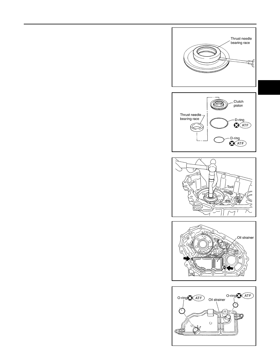
27. Remove the thrust needle bearing race from the clutch piston by

hooking a edge into 3 notches of the thrust needle bearing race

using suitable tool.

CAUTION:

Do not damage clutch piston or thrust needle bearing race.

28. Remove the two D-rings from the clutch piston.

29. Remove the mainshaft rear bearing from the center case using

Tool.

30. Remove the two bolts and oil strainer.

31. Remove the two O-rings from the oil strainer.

SDIA2118E

SDIA2781E

Tool number

: KV38100300 (J-25523)

SDIA2129E

SDIA2119E

SDIA2782E

2010 Pathfinder

DLN-166

< DISASSEMBLY AND ASSEMBLY >

[TRANSFER: ATX14B]

TRANSFER ASSEMBLY

32. Remove the snap ring. Then push the connector assembly into

the center case to remove the control valve assembly.

33. Remove the control valve assembly bolts.
34. Remove the control valve assembly.

CAUTION:

• Do not reuse any part that has been dropped or damaged.

• Make sure valve is assembled in the proper direction.

• Do not use a magnet because residual magnetism stays

during disassembly.

35. Remove the lip seals from the center case.

CAUTION:

There are two kinds of lip seals (lip seal of large inner diam-

eter: 5 pieces, lip seal of small inner diameter: 2 pieces).

Confirm the position before disassembly.

36. Remove the transfer motor bolts and motor from the center

case. Then remove the O-ring from the transfer motor.

37. Remove the sub oil pump cover bolts.

SDIA2122E

SDIA2121E

SDIA2123E

SDIA2133E

SDIA2134E

2010 Pathfinder

TRANSFER ASSEMBLY

DLN-167

< DISASSEMBLY AND ASSEMBLY >

[TRANSFER: ATX14B]

C

E

F

G

H

I

J

K

L

M

A

B

DLN

N

O

P

38. Thread two bolts (M4 x 0.8) into the holes of sub oil pump cover

as shown, and pull out to remove the sub oil pump assembly.

39. Remove the outer gear and inner gear from the sub oil pump

housing.

40. Remove the oil filter bolts and oil filter.

CAUTION:

• Do not damage center case and oil filter.

• Loosen bolts and detach oil filter evenly.

41. Remove the O-rings (1) from the oil filter (2).

42. Remove the oil filter stud from the oil filter.
43. Remove the O-ring from the oil filter stud.

SMT934C

SDIA2135E

SDIA2136E

WDIA0285E

SDIA3180E

2010 Pathfinder

DLN-168

< DISASSEMBLY AND ASSEMBLY >

[TRANSFER: ATX14B]

TRANSFER ASSEMBLY

Control Valve Assembly

1. Disassemble the control valve assembly with the following procedure.

CAUTION:

• Do not reuse any part that has been dropped or damaged.

• Make sure valve is assembled in the proper direction.

• Do not use a magnet because residual magnetism stays during disassembly.

a. Remove all the bolts except for the two shown.

b. Remove the following from the control valve assembly:

• Clutch pressure solenoid valve

• Clutch pressure switch

• 2-4WD shift solenoid valve

• Line pressure switch

• Transfer fluid temperature sensor

c.

Remove the O-rings from each solenoid valve, switch and termi-

nal body.

d. Place the control valve with the lower body facing up. Remove

the two bolts, and then remove the lower body and separator

plate from the upper body.

CAUTION:

Do not drop relief balls. Detach lower body carefully.

e. Make sure the reverse balls, relief balls, relief springs, accumu-

lator pistons and valve springs are securely installed as shown,

and remove them.

WDIA0198E

WDIA0199E

WDIA0200E

SDIA2126E

2010 Pathfinder

TRANSFER ASSEMBLY

DLN-169

< DISASSEMBLY AND ASSEMBLY >

[TRANSFER: ATX14B]

C

E

F

G

H

I

J

K

L

M

A

B

DLN

N

O

P

f.

Remove the retainer plates.

g. Remove each retainer plate (1), plug (2), control valve (3) and

spring (4) from the upper body (5).

INSPECTION AFTER DISASSEMBLY

Shift Rod Components

• Check the working face of the shift rod and fork for wear, partial

wear, bending and other abnormality. If any is found, replace with a

new one.

• Measure the clearance between the shift fork and sleeve. If it is out

of specification, replace it with a new one.

Planetary Carrier

SDIA2127E

WDIA0284E

SMT009D

Specification

Refer to 

DLN-189, "Inspection 

and Adjustment"

SMT010D

2010 Pathfinder

DLN-170

< DISASSEMBLY AND ASSEMBLY >

[TRANSFER: ATX14B]

TRANSFER ASSEMBLY

• Measure the end play of each pinion gear. If it is out of specifica-

tion, replace the planetary carrier assembly with a new one.

• Check the working face of each gear and bearing for damage,

burrs, partial wear, dents and other abnormality. If any is found,

replace the planetary carrier assembly with a new one.

Sun Gear

• Check if the oil passage of the sun gear assembly is clogged. For

this, try to pass a 3.6 mm (0.142 in) dia. pin through the oil pas-

sage as shown.

• Check the sliding and contact surface of each gear and bearing for

damage, burrs, partial wear, dents, and other abnormality. If any is

found, replace the sun gear assembly with a new one.

Internal Gear

• Check the internal gear teeth for damage, partial wear, dents and

other abnormality. If any is found, replace the internal gear with a

new one.

Gears and Drive Chain

• Check the gear faces and shaft for wear, cracks, damage, and sei-

zure.

• Check the surfaces which contact the sun gear, clutch drum, clutch

hub, press flange, clutch piston and each bearing for damage,

peel, partial wear, dents, bending, or other abnormal damage. If

any is found, replace with a new one.

Bearing

Pinion gear end play

Refer to 

DLN-189, "Inspection 

and Adjustment"

PDIA0185E

PDIA0186E

SMT008D

SMT944C

2010 Pathfinder

TRANSFER ASSEMBLY

DLN-171

< DISASSEMBLY AND ASSEMBLY >

[TRANSFER: ATX14B]

C

E

F

G

H

I

J

K

L

M

A

B

DLN

N

O

P

• Make sure the bearings roll freely and are free from noise, pitting

and cracks.

Main Oil Pump

1. Check the inner and outer circumference, tooth face, and side-

face of the inner and outer gears for damage or abnormal wear.

2. Measure the side clearance between the main oil pump housing

edge and the inner and outer gears.

3. Make sure the side clearance is within specification. If the mea-

surement is out of specification, replace the inner and outer

gears with new ones as a set. Refer to 

DLN-189, "Inspection

and Adjustment"

.

Sub-oil Pump

1. Check the inner and outer circumference, tooth face, and side-

face of the inner and outer gears for damage or abnormal wear.

2. Measure the side clearance between the sub oil pump housing

edge and the inner and outer gears.

3. Make sure the side clearance is within specification. If the mea-

surement is out of specification, replace the inner and outer

gears with new ones as a set. Refer to 

DLN-189, "Inspection

and Adjustment"

.

Control Valve

• Check resistance between the terminals of the clutch pressure

solenoid valve, 2-4WD shift solenoid valve, clutch pressure switch,

line pressure switch and the transfer fluid temperature sensor.

Refer to 

DLN-63, "Component Inspection"

 (clutch pressure sole-

noid valve), 

DLN-67, "Component Inspection"

 (2-4WD solenoid

valve), 

DLN-79, "Component Inspection"

 (clutch pressure switch),

DLN-82, "Component Inspection"

 (line pressure switch) and 

DLN-

75, "Component Inspection"

 (transfer fluid temperature sensor).

SDIA2175E

Specification

Refer to 

DLN-189, "Inspection and Ad-

justment"

SDIA2174E

Specification

Refer to 

DLN-189, "Inspection and Ad-

justment"

SDIA2173E

WDIA0199E

2010 Pathfinder

DLN-172

< DISASSEMBLY AND ASSEMBLY >

[TRANSFER: ATX14B]

TRANSFER ASSEMBLY

• Check the sliding faces of the control valves and plugs for abnor-

mality. If any is found, replace the control valve assembly with a

new one. Refer to 

DLN-189, "Inspection and Adjustment"

.

CAUTION:

Replace control valve body together with clutch return spring

as a set.

• Check each control valve spring for damage or distortion. Also

check its free length, outer diameter and wire diameter. If any dam-

age or fatigue is found, replace the control valve body with a new

one. Refer to 

DLN-189, "Inspection and Adjustment"

.

CAUTION:

Replace control valve body together with clutch return spring

as a set.

Clutch

• Check the drive plate facings and driven plate for damage, cracks

or other abnormality. If any abnormalities are found, replace with a

new one.

• Check the thickness of the drive plate facings and driven plate.

Refer to 

DLN-189, "Inspection and Adjustment"

.

CAUTION:

• Measure facing thickness at 3 points to take an average.

• Check all drive and driven plates.

• Check return spring for damage or deformation.

• Do not remove spring from plate.

Return Spring

• Check the stamped mark shown. Then, check that the free lengths,

(include thickness of plate) are within specifications. If any abnor-

mality is found, replace with a new return spring assembly of the

same stamped number. Refer to 

DLN-189, "Inspection and Adjust-

ment"

.

ASSEMBLY

Control Valve Assembly

1. Assemble the control valve assembly with the following procedure.

CAUTION:

• Do not reuse any part that has been dropped or damaged.

• Make sure valve is assembled in the proper direction.

• Do not use a magnet because residual magnetism stays during assembly.

SMT947C

SMT948C

SMT949C

SDIA2176E

2010 Pathfinder


Content      ..     197      198      199      200     ..