Nissan Pathfinder (2010 year). Manual - part 197


  Index      Manuals     Nissan Pathfinder (2010 year) - Service and Repair Manual


Search            copyright infringement  


Content      ..     195      196      197      198     ..


Nissan Pathfinder (2010 year). Manual - part 197


AIR BREATHER HOSE

DLN-149

< ON-VEHICLE REPAIR >

[TRANSFER: ATX14B]

C

E

F

G

H

I

J

K

L

M

A

B

DLN

N

O

P

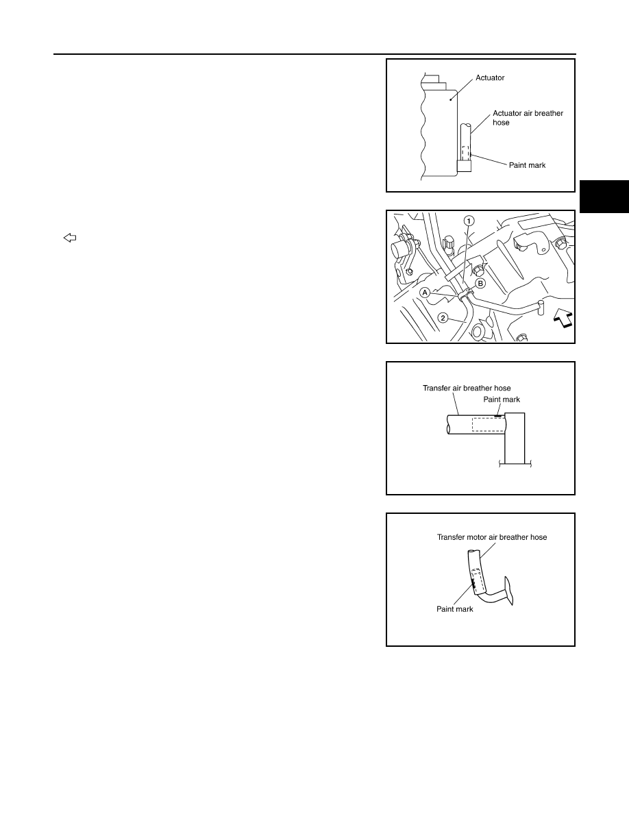
• Install the actuator air breather hose into the actuator (case

connector) until the hose end reaches the base of the tube.

Set actuator air breather hose with paint mark facing leftward.

• Install clip (A) on transfer motor air breather hose (2) and

transfer air breather hose (1) with the paint mark (B) matched.

: Front

• Install the transfer air breather hose into the breather tube

(transfer, metal connector) until the hose end reaches the

base of the tube. Set transfer air breather hose with paint

mark facing upwards.

• Install the transfer motor air breather hose into the transfer

motor (case connector) until the hose end reaches the end of

the curved section. Set transfer motor air breather hose with

paint mark facing leftward.

SDIA3226E

AWDIA0013ZZ

SDIA3196E

SDIA3194E

2010 Pathfinder

DLN-150

< ON-VEHICLE REPAIR >

[TRANSFER: ATX14B]

TRANSFER MOTOR

TRANSFER MOTOR

Removal and Installation

INFOID:0000000005258354

REMOVAL

1. Disconnect the transfer motor connector.
2. Remove the transfer motor air breather hose from the transfer

motor. Refer to 

DLN-145, "Removal and Installation"

.

3. Remove the transfer motor bolts.
4. Remove the transfer motor.

INSTALLATION

1. Apply ATF to the new O-ring and install it to the transfer motor.

CAUTION:

Do not reuse O-rings.

2. Fit the double-flat end of the transfer motor shaft into the slot of

the sub-oil pump assembly. Then tighten to the specified torque.

Refer to 

DLN-154, "Disassembly and Assembly"

.

CAUTION:

Be sure to install connector bracket.

3. Install the transfer motor air breather hose to the transfer motor.

Refer to 

DLN-145, "Removal and Installation"

.

4. Connect the transfer motor connector.
5. Check the transfer fluid. Refer to 

DLN-135, "Inspection"

.

6. Start the engine for one minute. Then stop the engine and recheck the transfer fluid. Refer to 

DLN-135,

"Inspection"

.

SDIA2133E

SDIA2787E

2010 Pathfinder

TRANSFER ASSEMBLY

DLN-151

< REMOVAL AND INSTALLATION >

[TRANSFER: ATX14B]

C

E

F

G

H

I

J

K

L

M

A

B

DLN

N

O

P

REMOVAL AND INSTALLATION

TRANSFER ASSEMBLY

Removal and Installation

INFOID:0000000005258355

REMOVAL

1. Set transfer state as 2WD when 4WD shift switch is at 2WD.
2. Remove the undercovers using power tool.
3. Drain the transfer fluid. Refer to 

DLN-135, "Replacement"

.

4. Remove the center exhaust tube and main muffler. Refer to 

EX-7, "Removal and Installation"

.

5. Remove the front and rear propeller shafts. Refer to 

DLN-315, "Removal and Installation"

 (front), 

DLN-

325, "Removal and Installation"

 or 

DLN-336, "Removal and Installation"

 (rear).

CAUTION:

Do not damage spline, sleeve yoke and rear oil seal when removing rear propeller shaft.

NOTE:

Insert a plug into the rear oil seal after removing the rear propeller shaft.

6. Remove the A/T nuts from the A/T crossmember. Refer to 

TM-194, "4WD : Exploded View"

.

7. Position two suitable jacks under the A/T and transfer assembly.
8. Remove the crossmember. Refer to 

TM-194, "4WD : Exploded View"

.

WARNING:

Support A/T and transfer assembly using two suitable jacks while removing crossmember.

9. Disconnect the electrical connectors from the following:

• ATP switch

• Neutral 4LO switch

• Wait detection switch

• Transfer motor

• Transfer control device

• Transfer terminal cord assembly

10. Remove transfer wiring harness.
11. Disconnect each air breather hose from the following. Refer to 

DLN-145, "Removal and Installation"

.

• Actuator

• Breather tube (transfer)

• Transfer motor

12. Remove the transfer control device from the extension housing.
13. Remove the transfer to A/T and A/T to transfer bolts.
14. Remove the transfer assembly.

WARNING:

Support transfer assembly with suitable jack while removing it.

CAUTION:

Do not damage rear oil seal (A/T).

INSTALLATION

Installation is in the reverse order of removal.

• Tighten the bolts to specification.

• Fill the transfer with new fluid and check for fluid leakage and fluid

level. Refer to 

DLN-135

.

• Start the engine for one minute. Then stop the engine and recheck

the transfer fluid. Refer to 

DLN-135, "Inspection"

.

Transfer bolt torque

: 36 N·m (3.7 kg-m, 27 ft-lb)

SMT872C

2010 Pathfinder

DLN-152

< DISASSEMBLY AND ASSEMBLY >

[TRANSFER: ATX14B]

TRANSFER ASSEMBLY

DISASSEMBLY AND ASSEMBLY

TRANSFER ASSEMBLY

Component Parts Location

INFOID:0000000005576260

1.

2-4 sleeve

2.

L-H sleeve

3.

Snap ring

4.

Internal gear

5.

Planetary carrier assembly

6.

Metal bushing

7.

Needle bearing

8.

Sun gear

9.

Carrier bearing

10.

Snap ring

11.

Snap ring

12.

Input bearing

13.

Wait detection switch

14.

Check plug

15.

Check spring

16.

Check ball

17.

Front case

18.

Snap ring

19.

Input oil seal

20.

Shift cross

21.

Side oil seal

22.

Lock pin

23.

Shift lever

24.

Gasket

25.

Drain plug

26.

Front oil seal

27.

Companion flange

28.

Self-lock nut

29.

Mainshaft

30.

Needle bearing

31.

Front bearing

32.

Front drive shaft

33.

Rear bearing

34.

Spacer

35.

Drive chain

36.

Clutch drum

37.

Snap ring

38.

Clutch hub 

39.

Snap ring

40.

Retaining plate

41.

Driven plate (10 sheet)

42.

Drive plate (10 sheet)

43.

Return spring assembly

44.

Press flange

45.

Thrust needle bearing

AWDIA0752GB

2010 Pathfinder

TRANSFER ASSEMBLY

DLN-153

< DISASSEMBLY AND ASSEMBLY >

[TRANSFER: ATX14B]

C

E

F

G

H

I

J

K

L

M

A

B

DLN

N

O

P

46.

Snap ring

47.

Retaining pin

48.

L-H fork

49.

2-4 fork

50.

Shift fork spring

51.

Fork guide

52.

Retainer pin

53.

Shift rod

A.

Apply Genuine Anaerobic Liquid 
Gasket, Three Bond TB1133c or 
equivalent

B.

Apply Genuine Liquid Gas-
ket, Three Bond TB1215 or 
equivalent

1.

Dust cover

2.

Rear oil seal

3.

Rear case

4.

Breather tube

5.

Seal ring

6.

Main oil pump cover

7.

Inner gear

8.

Outer gear

9.

Main oil pump housing

10.

D-ring

11. D-ring

12.

Clutch piston

13.

Thrust needle bearing race

14. Oil strainer

15.

O-ring

16.

Snap ring

17. Control valve assembly

18.

Lip seal (large 5 pieces)

19.

Lip seal (small 2 pieces)

20. Gasket

21.

Filler plug

22.

Oil filter stud

23. O-ring

24.

Oil filter

25

ATP switch

26. Neutral-4LO switch

27.

Oil pressure check plug

28.

Harness bracket

29. Air breather hose clamp

30.

Stem bleeder

31.

Harness bracket

32. Center case

33.

Mainshaft rear bearing

34.

C-ring

35. Washer holder

36.

Snap ring

WDIA0302E

2010 Pathfinder

DLN-154

< DISASSEMBLY AND ASSEMBLY >

[TRANSFER: ATX14B]

TRANSFER ASSEMBLY

Disassembly and Assembly

INFOID:0000000005258356

DISASSEMBLY

Rear Case

1. Remove the rear case bolts.

2. Remove the rear case from the center case.

3. Remove the dust cover using suitable tool.

4. Remove the rear oil seal using suitable tool.

CAUTION:

Do not damage rear case.

5. Remove the breather tube.

37.

Sub oil pump housing

38. Outer gear

39.

Inner gear

40.

Sub oil pump cover

41. O-ring

42.

Transfer motor

43.

Connector bracket

A.

Apply Genuine Anaerobic Liquid 
Gasket, Three Bond TB1133C or 
equivalent.

B.

Apply Genuine Liquid Gasket, 
Three Bond TB1215 or equiva-
lent.

SDIA2092E

SDIA2093E

SDIA2094E

SDIA2095E

2010 Pathfinder

TRANSFER ASSEMBLY

DLN-155

< DISASSEMBLY AND ASSEMBLY >

[TRANSFER: ATX14B]

C

E

F

G

H

I

J

K

L

M

A

B

DLN

N

O

P

Front Case

1. Remove the rear case assembly. Refer to 

DLN-154, "Disassembly and Assembly"

.

2. Remove the lock pin nut.
3. Remove the lock pin using suitable tool.
4. Remove the shift lever.

5. Remove the side oil seal from the front case using suitable tool.

CAUTION:

Do not damage front case or shift cross.

6. Remove the check plug, check spring and check ball.
7. Remove the wait detection switch.

8. Remove the self-lock nut from the companion flange using suit-

able tool.

SDIA2150E

SDIA2166E

WDIA0196E

SDIA2841E

2010 Pathfinder

DLN-156

< DISASSEMBLY AND ASSEMBLY >

[TRANSFER: ATX14B]

TRANSFER ASSEMBLY

9. Put a matching mark on top of the front drive shaft thread in line

with the mark on the companion flange.

CAUTION:

Use paint to make the matching mark on the front drive

shaft thread. Never damage the front drive shaft.

10. Remove the companion flange using suitable tool.

11. Remove the center case bolts, harness bracket and air breather.
12. Remove the filler plug and gasket.

13. Separate the center case from the front case. Then remove the

center case from the front case by prying it up using suitable

tool.

CAUTION:

Do not damage the mating surfaces.

14. Remove the shift rod components together with the 2-4 sleeve

and L-H sleeve.

15. Remove the shift cross from the front case, using shift rod (A).

SDIA2779E

WDIA0133E

SDIA2100E

SDIA2101E

AWDIA0015ZZ

2010 Pathfinder


Content      ..     195      196      197      198     ..