Nissan Pathfinder (2010 year). Manual - part 163
BACK DOOR LOCK
DLK-203
< ON-VEHICLE REPAIR >
[WITH INTELLIGENT KEY SYSTEM]
C
D
E
F
G
H
I
J
L
M
A
B
DLK
N
O
P
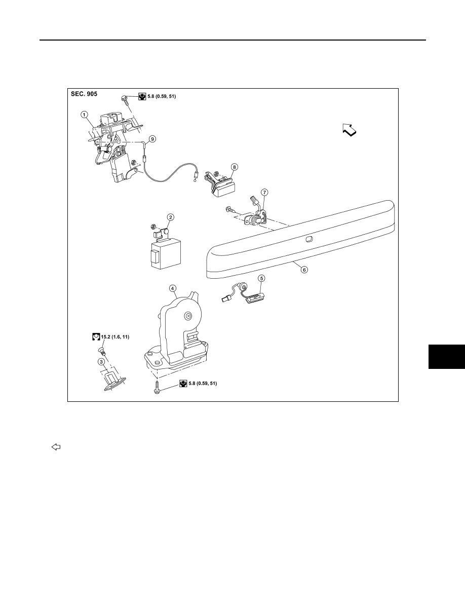
BACK DOOR LOCK
Component Structure
INFOID:0000000005260015
1.
Glass hatch latch assembly
2.
Back door control assembly
3.
Back door striker
4.
Back door latch assembly
5.
Back door release button
6.
Back door finisher
7.
Key button
8.
Glass hatch release handle
9.
Glass hatch release cable
Front
AWKIA1438GB
2010 Pathfinder