Nissan Pathfinder (2010 year). Manual - part 90
BCS
BCM (BODY CONTROL MODULE)
BCS-49
< ECU DIAGNOSIS >
C
D
E
F
G
H
I
J
K
L
B
A
O
P
N
1: With remote keyless entry system
2: With Intelligent Key system
60
LG
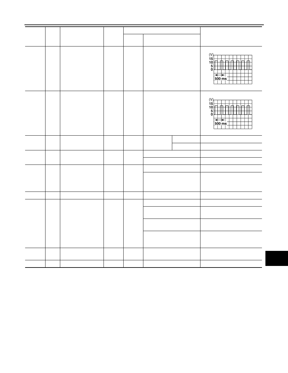
Turn signal (left)
Output
ON
Turn left ON
61
G
Turn signal (right)
Output
ON
Turn right ON
63
BR
Interior room/map
lamp
Output
OFF
Any door
switch
ON (open)
0V
OFF (closed)
Battery voltage
65
V
All door lock actuators
(lock)
Output
OFF
OFF (neutral)
0V
ON (lock)
Battery voltage
66
L
Front door lock actua-
tor RH, rear door lock
actuators LH/RH and
glass hatch lock actu-
ator (unlock)
Output
OFF
OFF (neutral)
0V
ON (unlock)
Battery voltage
67
B
Ground
Input
ON
—
0V
68
O
Power window power
supply (RAP)
Output
—
Ignition switch ON
Battery voltage
Within 45 seconds after igni-
tion switch OFF
Battery voltage
More than 45 seconds after ig-
nition switch OFF
0V
When front door LH or RH is
open or power window timer
operates
0V
69
L
Power window power
supply
Output
—
—
Battery voltage
70
W
Battery power supply
Input
OFF
—
Battery voltage
Terminal
Wire
color
Signal name
Signal
input/
output
Measuring condition
Reference value or waveform
(Approx.)
Ignition
switch
Operation or condition
SKIA3009J
SKIA3009J
2010 Pathfinder