Nissan Pathfinder (2010 year). Manual - part 74
AV
REAR TWEETER
AV-399
< COMPONENT DIAGNOSIS >
[BOSE AUDIO WITH NAVIGATION]
C
D
E
F
G
H
I
J
K
L
M
B
A
O
P
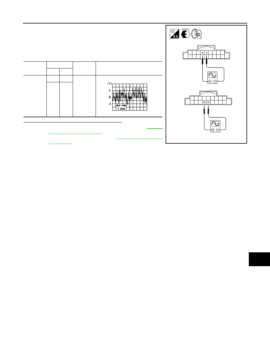
1. Connect AV control unit connector M39 and BOSE speaker
amp. connector B75.
2. Turn ignition switch to ACC.
3. Push “POWER” switch.
4. Check the signal between AV control unit harness connector
M39 terminals with CONSULT-III or oscilloscope.
Is the audio signal voltage reading as specified?
YES
>> Replace BOSE speaker amp. Refer to
.
NO
>> Replace AV control unit. Refer to
Connector
Terminals
Condition
Reference
signal
(+)
(-)
M39
4
5
Receive
audio sig-
nal
13
14
AWNIA0034ZZ
SKIA0177E
2010 Pathfinder
2010 Pathfinder