Nissan Pathfinder (2010 year). Manual - part 72


  Index      Manuals     Nissan Pathfinder (2010 year) - Service and Repair Manual


Search            copyright infringement  


Content      ..     70      71      72      73     ..


Nissan Pathfinder (2010 year). Manual - part 72


AV

RGB (B: BLUE) SIGNAL CIRCUIT

AV-383

< COMPONENT DIAGNOSIS >

[BOSE AUDIO WITH NAVIGATION]

C

D

E

F

G

H

I

J

K

L

M

B

A

O

P

RGB (B: BLUE) SIGNAL CIRCUIT

Description

INFOID:0000000005259589

Transmit the image displayed with AV control unit with RGB signal to the display unit.

Diagnosis Procedure

INFOID:0000000005259590

Regarding Wiring Diagram information, refer to 

AV-414, "Wiring Diagram"

.

1.

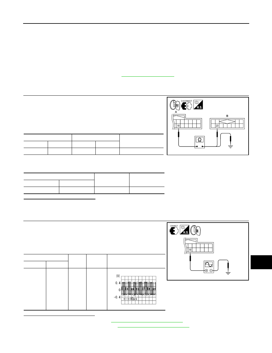
CHECK CONTINUITY RGB (B: BLUE) SIGNAL CIRCUIT

1. Turn ignition switch OFF.

2. Disconnect display unit connector M92 and AV control unit con-

nector M37.

3. Check continuity between display unit harness connector M92

(A) terminal 18 and AV control unit harness connector M37 (B)

terminal 23.

4. Check continuity between display unit harness connector M92

(A) terminal 18 and ground.

Are continuity results as specified?

YES

>> GO TO 2

NO

>> Repair harness or connector.

2.

CHECK RGB (B: BLUE) SIGNAL

1. Connect display unit connector M92 and AV control unit connec-

tor M37.

2. Turn ignition switch ON.

3. Check signal between display unit harness connector M92 ter-

minal 18 and ground.

Are voltage readings as specified?

YES

>> Replace display unit. Refer to 

AV-462, "Removal and Installation"

.

NO

>> Replace AV control unit. Refer to 

AV-460, "Removal and Installation"

.

A

B

Continuity

Connector

Terminal

Connector

Terminal

M92

18

M37

23

Yes

A

Continuity

Connector

Terminal

M92

18

Ground

No

AWNIA1791ZZ

(+)

(-)

Condition

Reference signal

Connector

Terminal

M92

18

Ground

Receive 
audio sig-
nal

ALNIA0387GB

SKIB2237J

2010 Pathfinder

2010 Pathfinder

AV-384

< COMPONENT DIAGNOSIS >

[BOSE AUDIO WITH NAVIGATION]

RGB SYNCHRONIZING SIGNAL CIRCUIT

RGB SYNCHRONIZING SIGNAL CIRCUIT

Description

INFOID:0000000005259591

Transmit the RGB synchronizing signal to the display unit so as to synchronize the RGB image displayed with

AV control unit.

Diagnosis Procedure

INFOID:0000000005259592

Regarding Wiring Diagram information, refer to 

AV-414, "Wiring Diagram"

.

1.

CHECK CONTINUITY RGB SYNCHRONIZING SIGNAL CIRCUIT

1. Turn ignition switch OFF.

2. Disconnect display unit connector M92 and AV control unit con-

nector M37.

3. Check continuity between display unit harness connector M92

(A) terminal 19 and AV control unit harness connector M37 (B)

terminal 25.

4. Check continuity between display unit harness connector M92

(A) terminal 19 and ground.

Are continuity results as specified?

YES

>> GO TO 2

NO

>> Repair harness or connector.

2.

CHECK RGB SYNCHRONIZING SIGNAL

1. Connect display unit connector M92 and AV control unit connec-

tor M37.

2. Turn ignition switch ON.

3. Check signal between display unit harness connector M92 ter-

minal 19 and ground.

Are voltage readings as specified?

YES

>> Replace display unit. Refer to 

AV-462, "Removal and Installation"

.

NO

>> Replace AV control unit. Refer to 

AV-460, "Removal and Installation"

.

A

B

Continuity

Connector

Terminal

Connector

Terminal

M92

19

M37

25

Yes

A

Continuity

Connector

Terminal

M92

19

Ground

No

AWNIA1792ZZ

(+)

(-)

Condition

Reference signal

Connector

Terminal

M92

19

Ground

Receive 
audio sig-
nal

ALNIA0389GB

SKIB3603E

2010 Pathfinder

2010 Pathfinder

AV

RGB AREA (YS) SIGNAL CIRCUIT

AV-385

< COMPONENT DIAGNOSIS >

[BOSE AUDIO WITH NAVIGATION]

C

D

E

F

G

H

I

J

K

L

M

B

A

O

P

RGB AREA (YS) SIGNAL CIRCUIT

Description

INFOID:0000000005259593

Transmits the display area of RGB image displayed by AV control unit with RGB area (YS) signal to display

unit.

Diagnosis Procedure

INFOID:0000000005259594

Regarding Wiring Diagram information, refer to 

AV-414, "Wiring Diagram"

.

1.

CHECK CONTINUITY RGB AREA (YS) SIGNAL CIRCUIT

1. Turn ignition switch OFF.

2. Disconnect display unit connector M92 and AV control unit con-

nector M37.

3. Check continuity between display unit harness connector M92

(A) terminal 9 and AV control unit harness connector M37 (B)

terminal 27.

4. Check continuity between display unit harness connector M92

(A) terminal 9 and ground.

Are continuity results as specified?

YES

>> GO TO 2

NO

>> Repair harness or connector.

2.

CHECK RGB SYNCHRONIZING SIGNAL

1. Connect display unit connector M92 and AV control unit connec-

tor M37.

2. Turn ignition switch ON.

3. Check signal between display unit harness connector M92 ter-

minal 9 and ground.

Are voltage readings as specified?

YES

>> Replace display unit. Refer to 

AV-462, "Removal and Installation"

.

NO

>> Replace AV control unit. Refer to 

AV-460, "Removal and Installation"

.

A

B

Continuity

Connector

Terminal

Connector

Terminal

M92

9

M37

27

Yes

A

Continuity

Connector

Terminal

M92

9

Ground

No

AWNIA1793ZZ

(+)

(-)

Condition

Reference signal

Connector

Terminal

M92

9

Ground

Receive 
audio sig-
nal

ALNIA0391GB

PKIB4948J

2010 Pathfinder

2010 Pathfinder

AV-386

< COMPONENT DIAGNOSIS >

[BOSE AUDIO WITH NAVIGATION]

HORIZONTAL SYNCHRONIZING (HP) SIGNAL CIRCUIT

HORIZONTAL SYNCHRONIZING (HP) SIGNAL CIRCUIT

Description

INFOID:0000000005259595

In composite image (AUX image, camera image), transmit the vertical synchronizing (VP) signal and horizon-

tal synchronizing (HP) signal from display unit to AV control unit so as to synchronize the RGB images dis-

played with AV control unit such as the image quality adjusting menu, etc.

Diagnosis Procedure

INFOID:0000000005259596

Regarding Wiring Diagram information, refer to 

AV-414, "Wiring Diagram"

.

1.

CHECK CONTINUITY HORIZONTAL SYNCHRONIZING (HP) SIGNAL CIRCUIT

1. Turn ignition switch OFF.

2. Disconnect display unit connector M92 and AV control unit con-

nector M37.

3. Check continuity between display unit harness connector M92

(A) terminal 8 and AV control unit harness connector M37 (B)

terminal 28.

4. Check continuity between display unit harness connector M92

(A) terminal 8 and ground.

Are continuity results as specified?

YES

>> GO TO 2

NO

>> Repair harness or connector.

2.

CHECK HORIZONTAL SYNCHRONIZING (HP) SIGNAL

1. Connect display unit connector M92 and AV control unit connec-

tor M37.

2. Turn ignition switch ON.

3. Check signal between display unit harness connector M92 ter-

minal 8 and ground.

Are voltage readings as specified?

YES

>> Replace AV control unit. Refer to 

AV-460, "Removal and Installation"

.

NO

>> Replace display unit. Refer to 

AV-462, "Removal and Installation"

.

A

B

Continuity

Connector

Terminal

Connector

Terminal

M92

8

M37

28

Yes

A

Continuity

Connector

Terminal

M92

8

Ground

No

AWNIA1794ZZ

(+)

(-)

Condition

Reference signal

Connector

Terminal

M92

8

Ground

Receive 
audio sig-
nal

ALNIA0396GB

SKIB3601E

2010 Pathfinder

2010 Pathfinder

AV

VERTICAL SYNCHRONIZING (VP) SIGNAL CIRCUIT

AV-387

< COMPONENT DIAGNOSIS >

[BOSE AUDIO WITH NAVIGATION]

C

D

E

F

G

H

I

J

K

L

M

B

A

O

P

VERTICAL SYNCHRONIZING (VP) SIGNAL CIRCUIT

Description

INFOID:0000000005259597

In composite image (AUX image, camera image), transmit the vertical synchronizing (VP) signal and horizon-

tal synchronizing (HP) signal from display unit to AV control unit so as to synchronize the RGB images dis-

played with AV control unit such as the image quality adjusting menu, etc.

Diagnosis Procedure

INFOID:0000000005259598

Regarding Wiring Diagram information, refer to 

AV-414, "Wiring Diagram"

.

1.

CHECK CONTINUITY VERTICAL SINCHRONIZING (VP) SIGNAL CIRCUIT

1. Turn ignition switch OFF.

2. Disconnect display unit connector M92 and AV control unit con-

nector M37.

3. Check continuity between display unit harness connector M92

(A) terminal 20 and AV control unit harness connector M37 (B)

terminal 29.

4. Check continuity between display unit harness connector M92

(A) terminal 20 and ground.

Are continuity results as specified?

YES

>> GO TO 2

NO

>> Repair harness or connector.

2.

CHECK VERTICAL SINCHRONIZING (VP) SIGNAL

1. Connect display unit connector M92 and AV control unit connec-

tor M37.

2. Turn ignition switch ON.

3. Check signal between display unit harness connector M92 ter-

minal 20 and ground.

Are voltage readings as specified?

YES

>> Replace AV control unit. Refer to 

AV-460, "Removal and Installation"

.

NO

>> Replace display unit. Refer to 

AV-462, "Removal and Installation"

.

A

B

Continuity

Connector

Terminal

Connector

Terminal

M92

20

M37

29

Yes

A

Continuity

Connector

Terminal

M92

20

Ground

No

AWNIA1795ZZ

(+)

(-)

Condition

Reference signal

Connector

Terminal

M92

20

Ground

Receive 
audio sig-
nal

ALNIA0393GB

SKIB3598E

2010 Pathfinder

2010 Pathfinder

AV-388

< COMPONENT DIAGNOSIS >

[BOSE AUDIO WITH NAVIGATION]

FRONT DOOR SPEAKER

FRONT DOOR SPEAKER

Description

INFOID:0000000005259599

The AV control unit sends audio signals to the BOSE speaker amp. The BOSE speaker amp. amplifies the

audio signals before sending them to the front door speakers using the audio signal circuits.

Diagnosis Procedure

INFOID:0000000005259600

Regarding Wiring Diagram information, refer to 

AV-414, "Wiring Diagram"

.

1.

HARNESS CHECK

1. Disconnect BOSE speaker amp. connector B75 and suspect

speaker connector.

2. Check continuity between BOSE speaker amp. harness connec-

tor B75 (A) and suspect speaker harness connector (B).

3. Check continuity between BOSE speaker amp. harness connec-

tor B75 (A) and ground.

Are continuity test results as specified?

YES

>> GO TO 2

NO

>> • Check connector housings for disconnected or loose terminals.

• Repair harness or connector.

2.

FRONT SPEAKER SIGNAL CHECK

A B

Continuity

Connector

Terminal

Connector

Terminal

B75

13

D12

1

Yes

14

2

15

D112

1

16

2

A

Continuity

Connector

Terminal

B75

13

Ground

No

14

15

15

ALNIA0530GB

2010 Pathfinder

2010 Pathfinder

AV

FRONT DOOR SPEAKER

AV-389

< COMPONENT DIAGNOSIS >

[BOSE AUDIO WITH NAVIGATION]

C

D

E

F

G

H

I

J

K

L

M

B

A

O

P

1. Connect BOSE speaker amp. connector B75 and suspect

speaker connector.

2. Turn ignition switch to ACC.

3. Push “POWER” switch.

4. Check the signal between BOSE speaker amp. harness connec-

tor B75 terminals with CONSULT-III or oscilloscope.

Is audio signal voltage as specified?

YES

>> Replace suspect speaker. Refer to 

AV-464, "Removal

and Installation"

.

NO

>> GO TO 3

3.

HARNESS CHECK

1. Disconnect AV control unit connector M39 and BOSE speaker

amp. connector B75.

2. Check continuity between AV control unit harness connector

M39 (A) and BOSE speaker amp. harness connector B75 (B).

3. Check continuity between AV control unit harness connector

M39 (A) and ground.

Are continuity test results as specified?

YES

>> GO TO 4

NO

>> • Check connector housings for disconnected or loose terminals.

• Repair harness or connector.

4.

FRONT SPEAKER SIGNAL CHECK

Connec-

tor

Terminal

Condition

Reference

signal

(+)

(-)

B75

13

14

Receive 
audio sig-
nal

15

16

ALNIA0531GB

SKIA0177E

A

B

Continuity

Connector

Terminal

Connector

Terminal

M39

2

B75

30

Yes

3

29

11

28

12

27

Continuity

Connector

Terminal

M39

2

Ground

No

3

11

12

ALNIA0550GB

2010 Pathfinder

2010 Pathfinder

AV-390

< COMPONENT DIAGNOSIS >

[BOSE AUDIO WITH NAVIGATION]

FRONT DOOR SPEAKER

1. Connect AV control unit connector and BOSE speaker amp.

connector.

2. Turn ignition switch ACC.

3. Push “POWER” switch.

4. Check the signal between AV control unit harness connector

M39 terminals with CONSULT-III or oscilloscope.

Are the audio signal voltage readings as specified?

YES

>> Replace BOSE speaker amp. Refer to 

AV-466,

"Removal and Installation"

.

NO

>> Replace AV control unit. Refer to 

AV-460, "Removal and

Installation"

.

Connector

Terminals

Condition

Reference

signal

(+)

(-)

M39

2

3

Receive 
audio sig-
nal

11

12

AWNIA0032ZZ

SKIA0177E

2010 Pathfinder

2010 Pathfinder


Content      ..     70      71      72      73     ..