Nissan Pathfinder (2010 year). Manual - part 71
AV
POWER SUPPLY AND GROUND CIRCUIT
AV-375
< COMPONENT DIAGNOSIS >
[BOSE AUDIO WITH NAVIGATION]
C
D
E
F
G
H
I
J
K
L
M
B
A
O
P
SUBWOOFER : Diagnosis Procedure
INFOID:0000000005259579
Regarding Wiring Diagram information, refer to
.
1.
CHECK FUSE
Check that the subwoofer fuse is not blown.
Is the fuse OK?
YES
>> GO TO 2
NO
>> Be sure to eliminate cause of malfunction before installing new fuse.
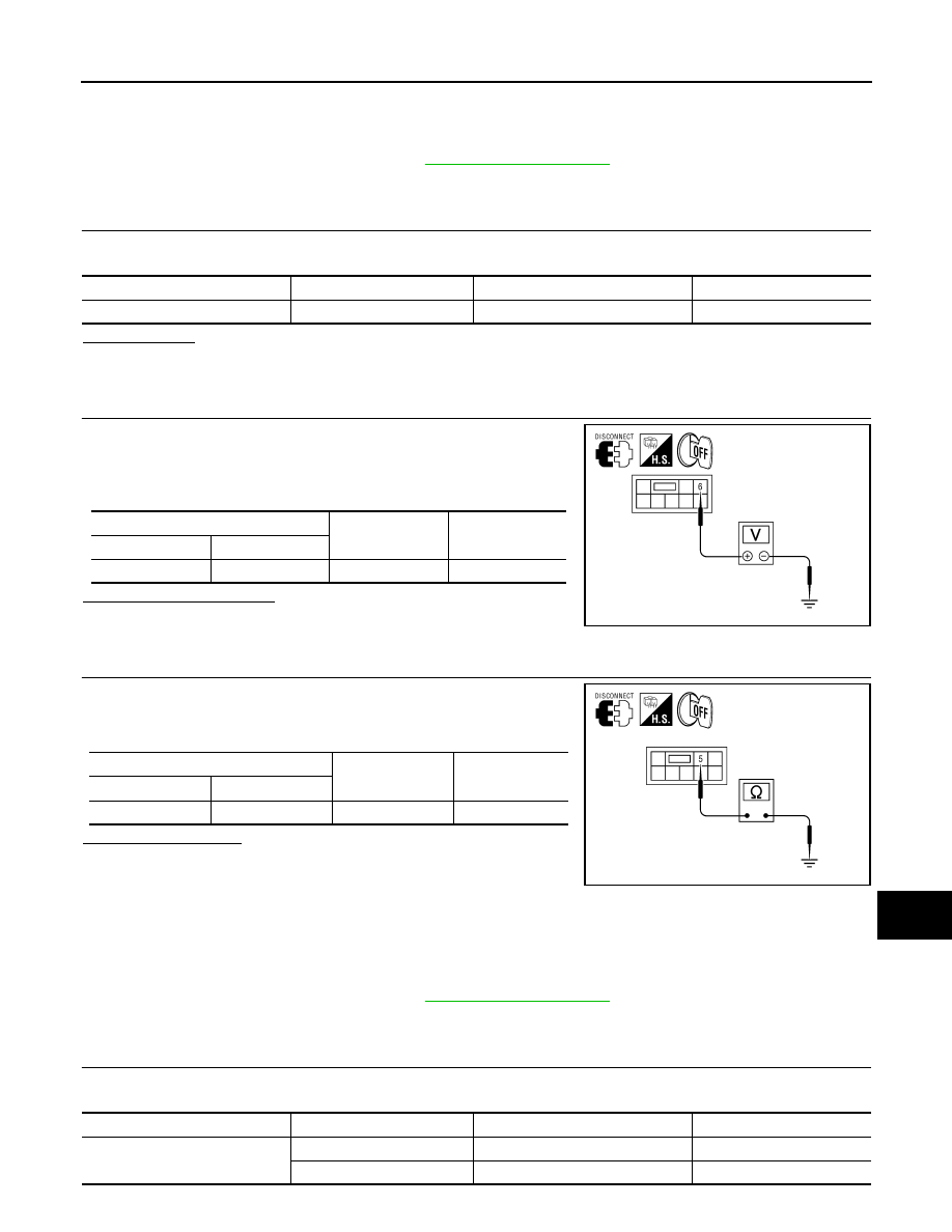
2.
CHECK POWER SUPPLY CIRCUIT
1. Turn ignition switch OFF.
2. Disconnect subwoofer connector.
3. Check voltage between subwoofer harness connector B72 ter-
minal 6 and ground.
Is battery voltage present?
YES
>> GO TO 3
NO
>> Check harness between subwoofer and fuse.
3.
CHECK GROUND CIRCUIT
1. Turn ignition switch OFF.
2. Check continuity between subwoofer harness connector B72
terminal 5 and ground.
Does continuity exist?
YES
>> Inspection End.
NO
>> Repair harness or connector.
REAR VIEW CAMERA CONTROL UNIT
REAR VIEW CAMERA CONTROL UNIT : Diagnosis Procedure
INFOID:0000000005259580
Regarding Wiring Diagram information, refer to
.
1.
CHECK FUSE
Check that the following fuses of the rear view camera control unit are not blown.
Unit
Terminal
Signal name
Fuse No.
Subwoofer
6
Battery power
17
(+)
(-)
Voltage (approx.)
Connector
Terminal
B72
6
Ground
Battery voltage
ALNIA0528GB
(+)
(-)
Continuity
Connector
Terminal
B72
5
Ground
Yes
ALNIA0529GB
Unit
Terminals
Signal name
Fuse No.
Rear view camera control unit
1
Battery power
29
2
Ignition switch ACC or ON
4
2010 Pathfinder
2010 Pathfinder