Nissan Pathfinder (2007 year). Manual - part 34
TRANSMISSION ASSEMBLY
AT-243
D
E
F
G
H
I
J
K
L
M
A
B
AT
2007 Pathfinder
Removal and Installation (4WD)
ECS00ELY
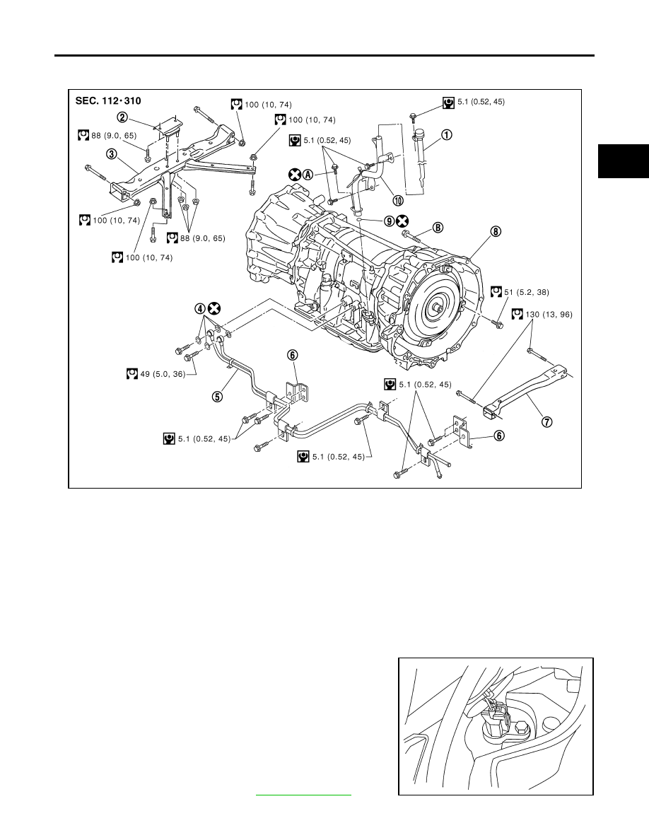
COMPONENTS
REMOVAL
CAUTION:
When removing the A/T assembly from engine, first remove the crankshaft position sensor (POS) from
the A/T assembly.
1.
Disconnect the negative battery terminal.
2.
Remove the A/T fluid level gauge.
3.
Remove the LH fender protector.
4.
Remove the crankshaft position sensor (POS) from the A/T
assembly.
CAUTION:
●
Do not subject it to impact by dropping or hitting it.
●
Do not disassemble.
●
Do not allow metal filings or foreign material to get on the
sensor's front edge magnetic area.
●
Do not place in an area affected by magnetism.
5.
Remove the undercovers using power tool.
6.
Partially drain the A/T fluid. Refer to
1.
A/T fluid level gauge
2.
Insulator
3.
A/T crossmember
4.
Copper washers
5.
A/T fluid cooler tube
6.
Bracket
7.
Front crossmember
8.
Transmission assembly
9.
O-ring
10.
A/T fluid charging pipe
A.
Self-sealing bolt
B.
Refer to installation.
WCIA0574E
LCIA0367E