Nissan Pathfinder (2007 year). Manual - part 33
ON-VEHICLE SERVICE
AT-235
D
E
F
G
H
I
J
K
L
M
A
B
AT
2007 Pathfinder
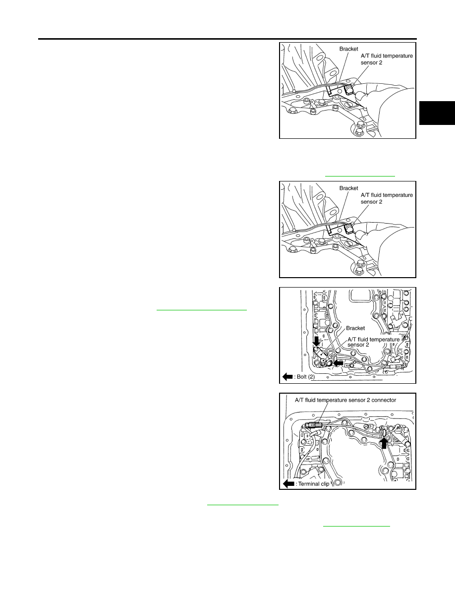
7.
Remove bracket from A/T fluid temperature sensor 2.
Installation
CAUTION:
After completing installation, check A/T fluid leakage and fluid level. Refer to
1.
Install A/T fluid temperature sensor 2 to bracket.
2.
Install A/T fluid temperature sensor 2 (with bracket) in control
valve with TCM. Tighten A/T fluid temperature sensor 2 bolt to
the specified torque. Refer to
CAUTION:
Adjust bolt hole of bracket to bolt hole of control valve with
TCM.
3.
Connect A/T fluid temperature sensor 2 connector.
4.
Securely fasten A/T fluid temperature sensor 2 harness with ter-
minal clip.
5.
Install oil pan to transmission case. Refer to
.
6.
Connect the negative battery terminal.
7.
Refill the A/T with fluid and check the fluid level and for fluid leakage. Refer to
.
SCIA5264E
SCIA5264E
SCIA5253E
SCIA5146E