Nissan Pathfinder (2006 year). Manual - part 396
PREPARATION
WT-3
C
D
F
G
H
I
J
K
L
M
A
B
WT
2006 Pathfinder
PREPARATION
PFP:00002
Special Service Tool
EES0023S
The actual shapes of Kent-Moore tools may differ from those of special service tools illustrated here.
Commercial Service Tools
EES0023T
Tool number
(Kent-Moore No.)
Tool name
Description
—
(J-45295)
Transmitter activation tool
ID registration
LEIA0035E
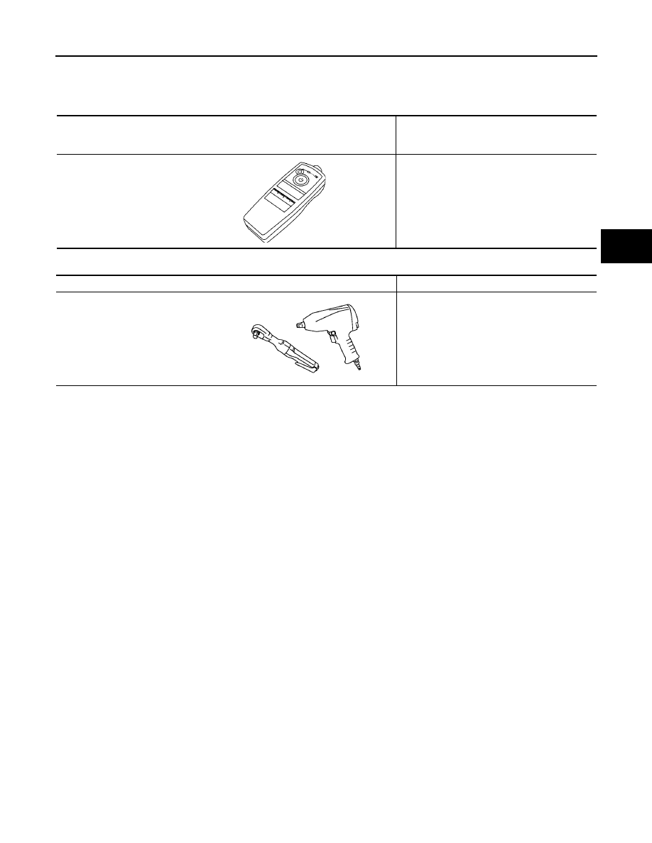
Tool name
Description
Power tool
Removing wheel nuts
PBIC0190E