Nissan Pathfinder (2006 year). Manual - part 394


  Index      Manuals     Nissan Pathfinder (2006 year) - Service and Repair Manual


Search            copyright infringement  


Content      ..     392      393      394      395     ..


Nissan Pathfinder (2006 year). Manual - part 394


FRONT PASSENGER AIR BAG MODULE

SRS-51

C

D

E

F

G

I

J

K

L

M

A

B

SRS

2006 Pathfinder

WIRING HARNESS MODIFICATION

The passenger air bag module originally installed in the vehicle uses direct-connect style harness connectors.
Service replacement passenger air bag modules use tab-locking style harness connectors. If the passenger
air bag module is replaced or if the direct-connect harness connectors are damaged, the vehicle wiring har-
ness must be modified to allow connection of the service replacement passenger air bag module.

NOTE:
The wiring harness modification is to be performed only if the vehicle is equipped with the original passenger
air bag which uses direct-connect harness connectors. If the passenger air bag is to be replaced in a vehicle
that has already had the service replacement passenger air bag installed, the wiring harness modification is
not required.

CAUTION:

Do not attempt to repair or replace damaged direct-connect front passenger air bag module con-
nectors. If a direct-connect harness connector is damaged, the front passenger air bag must be
replaced and the wiring harness modified.

Before servicing SRS, turn the ignition switch off, disconnect both battery cables and wait at least
3 minutes.

Always work from the side of or under front passenger air bag module.

After the work is completed, perform self-diagnosis to check that no malfunction is detected.
Refer to 

SRS-20, "SRS Operation Check"

 .

1.

Locate the yellow and orange direct-connect passenger air bag module harness connectors.

2.

Use wire cutters to cut back both previously used direct-connect passenger air bag module harness con-
nectors from the vehicle wiring harness approximately 50 mm (1.9 in) from the connectors.

3.

Remove approximately 150 mm (5.9 in) of the vehicle harness covering from the cut end.
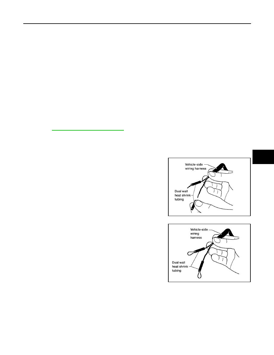
4.

Slide a piece of dual-wall heat shrink tubing (provided in the pas-
senger air bag service kit) onto each wire of the previously used
vehicle wiring harness.

5.

Fold each wire back and insert into the end of the heat shrink
tubing so that the end of the wire is approximately centered in
the heat shrink tubing.

6.

Use a heat gun to shrink the heat shrink tubing and seal the wire.

7.

Use electrical tape to secure the modified circuits to the outside of the wiring harness.

LHIA0017E

WHIA0062E

SRS-52

FRONT PASSENGER AIR BAG MODULE

2006 Pathfinder

8.

Locate the front passenger air bag service replacement connec-
tor that is taped back to the main harness. Unwrap the tape to
access the yellow service replacement connector and remove
the dust cover from the connector.

WHIA0118E

SIDE CURTAIN AIR BAG MODULE

SRS-53

C

D

E

F

G

I

J

K

L

M

A

B

SRS

2006 Pathfinder

SIDE CURTAIN AIR BAG MODULE

PFP:985P0

Removal and Installation

EHS001M9

REMOVAL

CAUTION:

Do not attempt to repair or replace damaged direct-connect SRS component connectors. If a
direct-connect harness connector is damaged, the harness must be replaced.

Before servicing the SRS, turn the ignition switch off, disconnect both battery cables and wait at
least 3 minutes.

When servicing the SRS, do not work from directly in front of air bag module.

1.

Remove headlining. Refer to 

EI-30, "Removal and Installation"

 .

2.

Disconnect front and rear side curtain air bag module connectors.

For removal/installation of the direct-connect SRS connectors, refer to 

SRS-7, "Direct-connect SRS

Component Connectors"

 .

3.

Remove the bolts in order starting at the front or rear, and remove the side curtain air bag module.

CAUTION:

When servicing the SRS, do not work from directly in front of air bag module.

Do not insert any foreign objects (screwdriver, etc.) into air bag module or harness connectors.

Do not disassemble air bag module.

Do not expose the air bag module to temperatures exceeding 90

°

C (194

°

F).

Replace side curtain air bag module if it has been dropped
or sustained an impact.

Do not allow oil, grease or water to come in contact with the
air bag module.

INSTALLATION

Installation is in the reverse order of removal.

WHIA0299E

1. 

Rear curtain air bag module connector

2.

Front curtain air bag module connector

3.

Sail panel extrusion

SBF814E

SRS-54

SIDE CURTAIN AIR BAG MODULE

2006 Pathfinder

For removal/installation of the direct-connect SRS connectors, refer to 

SRS-7, "Direct-connect SRS Com-

ponent Connectors"

 .

After replacement of side curtain air bag module, perform self-diagnosis to check that no malfunction is
detected. Refer to 

SRS-20, "SRS Operation Check"

 .

CRASH ZONE SENSOR

SRS-55

C

D

E

F

G

I

J

K

L

M

A

B

SRS

2006 Pathfinder

CRASH ZONE SENSOR

PFP:98531

Removal and Installation

EHS001MA

REMOVAL

CAUTION:

Before servicing the SRS, turn the ignition switch off, disconnect both battery cables and wait at
least 3 minutes.

1.

Disconnect the negative and positive battery cables, then wait at least 3 minutes.

2.

Remove crash zone sensor nuts and shield from support mem-
ber. 

3.

Disconnect the crash zone sensor harness connector.

4.

Remove crash zone sensor.

CAUTION:

Replace crash zone sensor if it has been dropped or sustained an impact.

Do not disassemble crash zone sensor.

INSTALLATION

Installation is in the reverse order of removal.

After the work is complete, perform self-diagnosis to check that no malfunction is detected. Refer to 

SRS-

20, "SRS Operation Check"

 .

LHIA0090E

SRS-56

SIDE AIR BAG (SATELLITE) SENSOR

2006 Pathfinder

SIDE AIR BAG (SATELLITE) SENSOR

PFP:98830

Removal and Installation

EHS001MB

REMOVAL

CAUTION:

Before servicing the SRS, turn the ignition switch off, disconnect both battery cables and wait at
least 3 minutes.

1.

Disconnect the negative and positive battery cables, then wait at least 3 minutes.

2.

Remove front door sill finisher and lift carpet.

3.

Remove side air bag (satellite) sensor nuts and release the clip.

4.

Disconnect the side air bag (satellite) sensor connector.

CAUTION:

Do not use old nuts after removal; replace with new nuts.

Check side air bag (satellite) sensor to ensure it is free of deformities, dents, cracks or rust. If it
shows any visible signs of damage, replace it with new one.

Do not disassemble side air bag (satellite) sensor.

Replace side air bag (satellite) sensor if it has been dropped or sustained an impact.

INSTALLATION

Installation is in the reverse order of removal.

After the work is completed, perform self-diagnosis to check that no malfunction is detected. Refer to

SRS-20, "SRS Operation Check"

 .

1.

Front seat finisher

2.

Side air bag (satellite) sensor

3.

Clip

4.

Nuts

5.

Side air bag (Satellite) sensor connector

LHIA0091E

FRONT SEAT BELT PRE-TENSIONER

SRS-57

C

D

E

F

G

I

J

K

L

M

A

B

SRS

2006 Pathfinder

FRONT SEAT BELT PRE-TENSIONER

PFP:86884

Removal and Installation 

EHS001MC

For removal and installation procedures, refer to 

SB-3, "Removal and Installation of Front Seat Belt"

 . 

SRS-58

DIAGNOSIS SENSOR UNIT

2006 Pathfinder

DIAGNOSIS SENSOR UNIT

PFP:28556

Removal and Installation

EHS001MD

REMOVAL

CAUTION:

Before servicing the SRS, turn the ignition switch off, disconnect both battery cables and wait at
least 3 minutes.

1.

Disconnect the negative and positive battery cables, then wait at least 3 minutes.

2.

Disconnect the connectors for each air bag module and seat belt pre-tensioner.

3.

Remove center console. Refer to 

IP-10, "INSTRUMENT PANEL ASSEMBLY"

 .

4.

Disconnect diagnosis sensor unit connectors.

5.

Remove bolts from the diagnosis sensor unit.

CAUTION:

Do not use old bolts; replace with new bolts.

Check diagnosis sensor unit bracket to ensure it is free of deformities, dents, cracks or rust. If it
shows any visible signs of damage, replace with new one.

Replace diagnosis sensor unit if it has been dropped or sustained an impact.

INSTALLATION

Installation is in the reverse order of removal.

After the work is completed, perform self-diagnosis to check that no malfunction is detected. Refer to

SRS-20, "SRS Operation Check"

 .

CAUTION:

The diagnosis sensor unit must always be installed with the arrow mark "

" pointing toward the

front of the vehicle for proper operation.

ECU DISCRIMINATED NO.

After replacing the diagnosis sensor unit, confirm that the diagnosis sensor unit identification is correct for the
vehicle as equipped. Refer to 

SRS-18, "CONSULT-II Function (AIR BAG)"

 .

WHIA0274E

1.

Diagnosis sensor unit connectors

2.

Diagnosis sensor unit


Content      ..     392      393      394      395     ..