Nissan Pathfinder (2006 year). Manual - part 316
COMBINATION SWITCH
LT-83
C
D
E
F
G
H
I
J
L
M
A
B
LT
2006 Pathfinder
3.
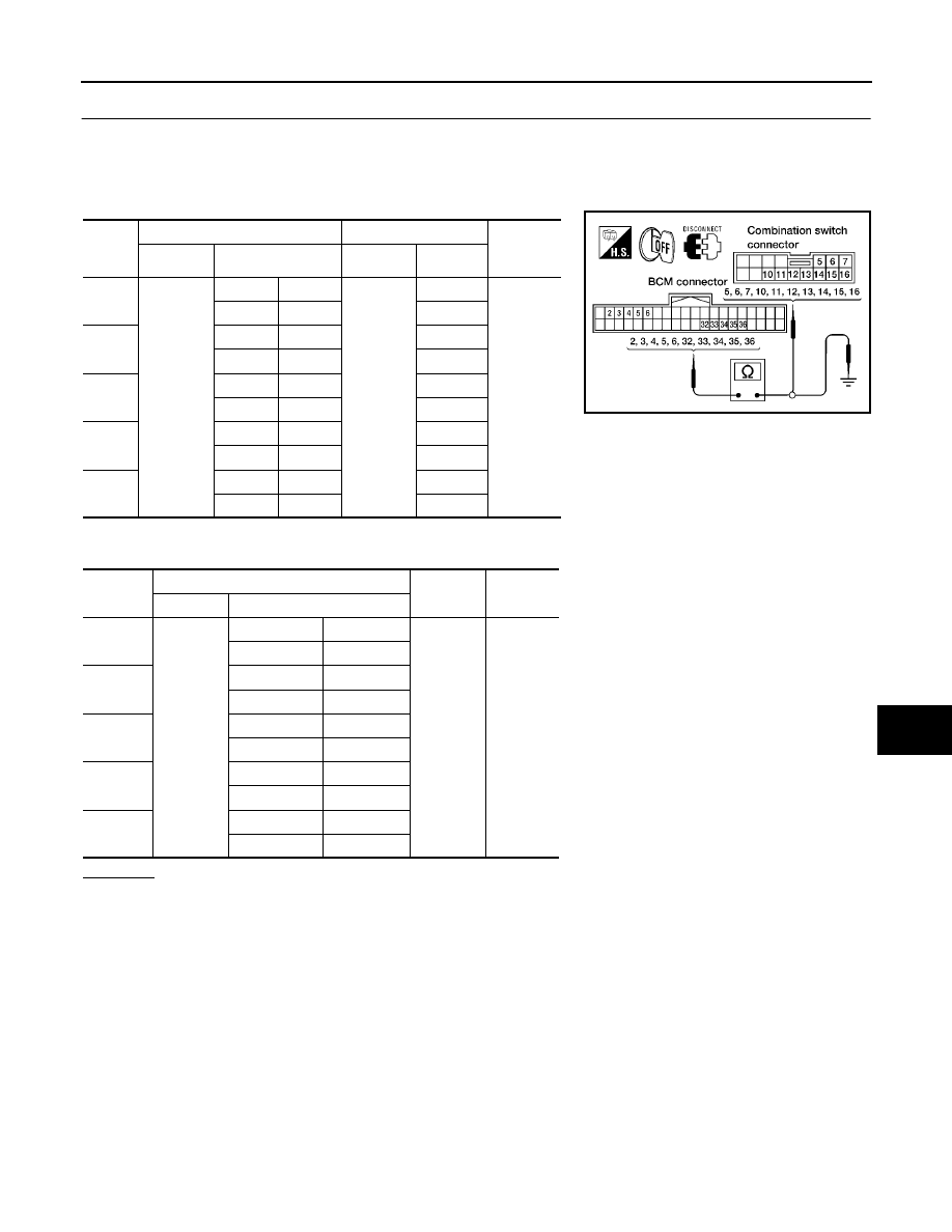
HARNESS INSPECTION
1.
Turn ignition switch OFF.
2.
Disconnect BCM and combination switch connectors.
3.
Check for continuity between BCM harness connector of the suspect system and the corresponding com-
bination switch connector terminals.
4.
Check for continuity between each terminal of BCM harness connector in suspect malfunctioning system
and ground.
OK or NG
OK
>> GO TO 4.
NG
>> Check harness between BCM and combination switch for open or short circuit.
Sus-
pect
system
BCM
Combination switch
Continuity
Connector
Terminal
Connector
Terminal
1
M18
Input 1
6
M28
10
Yes
Output 1
36
13
2
Input 2
5
15
Output 2
35
12
3
Input 3
4
5
Output 3
34
16
4
Input 4
3
6
Output 4
33
11
5
Input 5
2
7
Output 5
32
14
Suspect
system
BCM
Continuity
Connector
Terminal
1
M18
Input 1
6
Ground
No
Output 1
36
2
Input 2
5
Output 2
35
3
Input 3
4
Output 3
34
4
Input 4
3
Output 4
33
5
Input 5
2
Output 5
32
WKIA4021E