Nissan Pathfinder (2005 year). Manual - part 442
TRANSFER ASSEMBLY
TF-155
[ATX14B]
C
E
F
G
H
I
J
K
L
M
A
B
TF
2005 Pathfinder
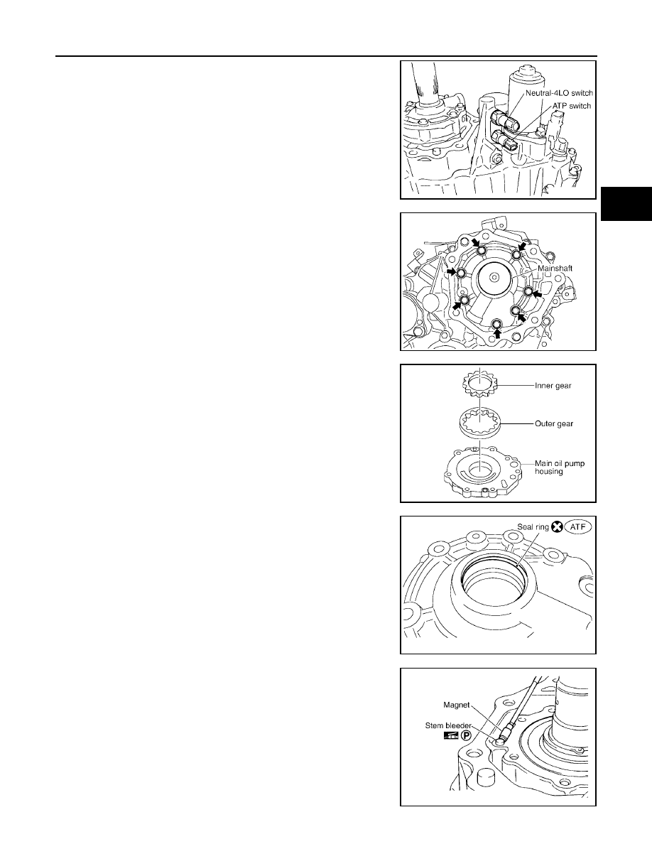
6.
Remove the neutral-4LO and ATP switches.
7.
Remove the bolts and main oil pump.
8.
Remove the outer gear and inner gear from the main oil pump
housing.
9.
Remove the seal ring from the main oil pump cover.
10. Remove the stem bleeder from the bleed hole.
SDIA2096E
SDIA2130E
SDIA2131E
SDIA2783E
SDIA2780E