Nissan Pathfinder (2005 year). Manual - part 357


  Index      Manuals     Nissan Pathfinder (2005 year) - Service and Repair Manual


Search            copyright infringement  


Content      ..     355      356      357      358     ..


Nissan Pathfinder (2005 year). Manual - part 357


TROUBLE DIAGNOSIS

MTC-47

C

D

E

F

G

H

I

K

L

M

A

B

MTC

2005 Pathfinder

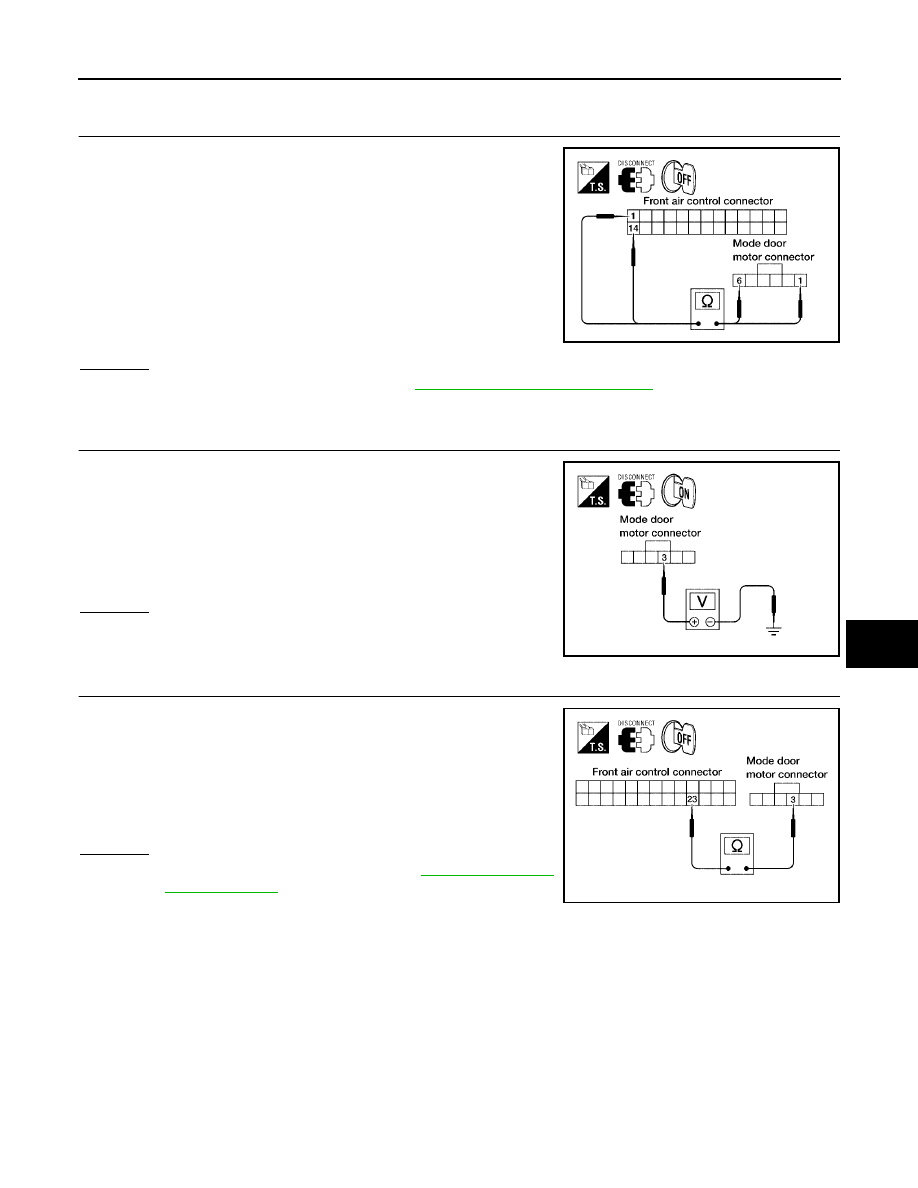
DIAGNOSTIC PROCEDURE FOR MODE DOOR MOTOR

1.

CHECK POWER SUPPLY AND GROUND CIRCUITS FOR MODE DOOR MOTOR

1.

Turn ignition switch OFF.

2.

Disconnect front air control connector and mode door motor
connector.

3.

Check continuity between front air control harness connector
M49 terminal 1 and mode door motor harness connector M142
terminal 1 and between front air control harness connector M49
terminal 14 and mode door motor harness connector M142 ter-
minal 6.

OK or NG

OK

>> Replace mode door motor. Refer to

MTC-90, "MODE DOOR MOTOR"

NG

>> Repair or replace harness as necessary.

2.

CHECK PBR REFERENCE SIGNAL VOLTAGE

1.

Turn ignition switch OFF.

2.

Disconnect the mode door motor connector.

3.

Turn ignition switch ON.

4.

Check voltage between mode door motor harness connector
M142 terminal 3 and ground.

OK or NG

OK

>> GO TO 5.

NG

>> GO TO 4.

3.

CHECK PBR REFERENCE VOLTAGE CIRCUIT BETWEEN MODE DOOR AND FRONT AIR CONTROL

1.

Turn ignition switch OFF.

2.

Disconnect the front air control connector.

3.

Check continuity between mode door motor harness connector
M142 terminal 3 and front air control harness connector M49 ter-
minal 23.

OK or NG

OK

>> Replace front air control. Refer to

ATC-124, "FRONT

AIR CONTROL"

.

NG

>> Repair or replace harness as necessary.

1 - 1

: Continuity should exist.

14 - 6

: Continuity should exist.

WJIA1241E

3 - Ground

: Approx. 5V

WJIA1242E

3 - 23

: Continuity should exist.

WJIA1085E

MTC-48

TROUBLE DIAGNOSIS

2005 Pathfinder

4.

CHECK PBR GROUND REFERENCE CIRCUIT

1.

Turn ignition switch OFF.

2.

Disconnect the front air control connector.

3.

Check continuity between mode door motor harness connector
M142 terminal 2 and front air control harness connector M49 ter-
minal 26.

OK or NG

OK

>> GO TO 6.

NG

>> Repair or replace harness as necessary.

5.

CHECK PBR FEEDBACK SIGNAL

1.

Reconnect the front air control connector and mode door motor
connector.

2.

Turn ignition switch ON.

3.

Check voltage between front air control harness connector M49
terminal 21 and ground.

4.

Press mode switch through all modes.

OK or NG

OK

>> Replace front air control. Refer to

ATC-124, "FRONT

AIR CONTROL"

.

NG

>> GO TO 7.

6.

CHECK PBR FEEDBACK CIRCUIT

1.

Turn ignition switch OFF.

2.

Disconnect the mode door motor connector and front air control
harness connector.

3.

Check continuity between mode door motor harness connector
M142 terminal 4 and front air control harness connector M49 ter-
minal 21.

OK or NG

OK

>> Replace mode door motor. Refer to

ATC-141, "MODE

DOOR MOTOR"

.

NG

>> Repair or replace harness as necessary.

2 - 26

: Continuity should exist.

WJIA1087E

21 - Ground

: Approx. 0 - 5V

WJIA1088E

4 - 21

: Continuity should exist.

WJIA1089E

TROUBLE DIAGNOSIS

MTC-49

C

D

E

F

G

H

I

K

L

M

A

B

MTC

2005 Pathfinder

Air Mix Door Motor Circuit

EJS003VH

SYMPTOM:

Discharge air temperature does not change.

Air mix door motor does not operate.

INSPECTION FLOW

*1

MTC-40, "Operational Check"

*2

MTC-51, "DIAGNOSTIC PROCE-
DURE FOR AIR MIX DOOR
MOTOR (FRONT)"

.

WJIA1315E

MTC-50

TROUBLE DIAGNOSIS

2005 Pathfinder

SYSTEM DESCRIPTION
Component Parts

Air mix door control system components are:

Front air control.

Air mix door motor

PBR (built into air mix door motor)

Intake sensor

System Operation

The front air control receives data from the temperature selected by the driver. The front air control then
applies a voltage to one circuit of the air mix door motor, while ground is applied to the other circuit, causing
the air mix door motor to rotate. The direction of rotation is determined by which circuit has voltage applied to
it, and which one has ground applied to it. The front air control monitors the air mix door positions by measur-
ing the voltage signal on the PBR circuits of each door.

Air Mix Door Control Specification

COMPONENT DESCRIPTION
Air Mix Door Motors

The air mix door motor is attached to the front heater & cooling unit.
This motor rotates so that the air mix door is opened or closed to a
position set by the front air control. Motor rotation is then conveyed
through a shaft and the air mix door position is then fed back to the
front air control by the PBR built into the air mix door motor.

WJIA1316E

WJIA0435E

WJIA1317E

TROUBLE DIAGNOSIS

MTC-51

C

D

E

F

G

H

I

K

L

M

A

B

MTC

2005 Pathfinder

DIAGNOSTIC PROCEDURE FOR AIR MIX DOOR MOTOR (FRONT)

1.

CHECK POWER SUPPLY CIRCUITS FOR AIR MIX DOOR MOTOR

1.

Turn ignition switch OFF.

2.

Disconnect front air control connector and air mix door motor
(front) connector.

3.

Check continuity between front air control harness connector
M49 terminal 2 and 3 and air mix door motor (front) harness
connector M147 terminal 6 and 5.

OK or NG

OK

>> Replace air mix door motor (front). Refer to

MTC-91,

"AIR MIX DOOR MOTOR"

.

NG

>> Repair or replace harness as necessary.

2.

CHECK PBR REFERENCE SIGNAL VOLTAGE

1.

Turn ignition switch OFF.

2.

Disconnect the air mix door motor (front) connector.

3.

Turn ignition switch ON.

4.

Check voltage between air mix door motor (front) harness con-
nector M147 terminal 1 and ground.

OK or NG

OK

>> GO TO 4.

NG

>> GO TO 3.

3.

CHECK PBR REFERENCE VOLTAGE CIRCUIT BETWEEN AIR MIX DOOR MOTOR (FRONT) AND

FRONT AIR CONTROL

1.

Turn ignition switch OFF.

2.

Disconnect the front air control connector.

3.

Check continuity between air mix door motor (front) harness
connector M147 terminal 1 and front air control harness connec-
tor M49 terminal 23.

OK or NG

OK

>> Replace front air control. Refer to

ATC-124, "FRONT

AIR CONTROL"

.

NG

>> Repair or replace harness as necessary.

2 - 6

: Continuity should exist.

3 - 5

: Continuity should exist.

WJIA1318E

1 - Ground

: Approx. 5V

WJIA1319E

1 - 23

: Continuity should exist.

WJIA1467E

MTC-52

TROUBLE DIAGNOSIS

2005 Pathfinder

4.

CHECK PBR GROUND REFERENCE CIRCUIT

1.

Turn ignition switch OFF.

2.

Disconnect the front air control connector.

3.

Check continuity between air mix door motor (front) harness
connector M147 terminal 3 and front air control harness connec-
tor M49 terminal 26.

OK or NG

OK

>> GO TO 5.

NG

>> Repair or replace harness as necessary.

5.

CHECK PBR FEEDBACK SIGNAL

1.

Reconnect the front air control connector and air mix door motor
(front) connector.

2.

Turn ignition switch ON.

3.

Check voltage between front air control harness connector M49
terminal 22 and ground.

4.

Rotate driver temperature control dial through complete range.

OK or NG

OK

>> Replace front air control. Refer to

ATC-124, "FRONT

AIR CONTROL"

.

NG

>> GO TO 6.

6.

CHECK PBR FEEDBACK CIRCUIT

1.

Turn ignition switch OFF.

2.

Disconnect the air mix door motor (front) connector and front air
control connector.

3.

Check continuity between air mix door motor (front) harness
connector M147 terminal 2 and front air control harness connec-
tor M49 terminal 22.

OK or NG

OK

>> Replace air mix door motor (front). Refer to

MTC-91,

"AIR MIX DOOR MOTOR"

.

NG

>> Repair or replace harness as necessary.

3 - 26

: Continuity should exist.

WJIA1320E

22 - Ground

: Approx. 0V - 5V

WJIA1096E

2 - 22

Continuity should exist.

WJIA1321E

TROUBLE DIAGNOSIS

MTC-53

C

D

E

F

G

H

I

K

L

M

A

B

MTC

2005 Pathfinder

Intake Door Motor Circuit

EJS003VI

SYMPTOM:

Intake door does not change.

Intake door motor does not operate normally.

INSPECTION FLOW

*1

ATC-52, "Operational Check
(Front)"

.

.

.

WJIA1322E

MTC-54

TROUBLE DIAGNOSIS

2005 Pathfinder

SYSTEM DESCRIPTION
Component Parts

Intake door control system components are:

Front air control

Intake door motor

Intake sensor

System Operation

The intake door control determines the intake door position based on the position of the recirculation switch.
When the recirculation switch is depressed the intake door motor rotates closing off the fresh air inlet and
recirculating the cabin air. If the recirculation switch is depressed again, the intake door motor rotates in the
opposite direction, again allowing fresh air into the cabin.

COMPONENT DESCRIPTION
Intake door motor

The intake door motor is attached to the intake unit. It rotates so that
air is drawn from inlets set by the front air control. Motor rotation is
conveyed to a lever which activates the intake door.

WJIA1323E

WJIA1107E


Content      ..     355      356      357      358     ..