Nissan Pathfinder (2005 year). Manual - part 340


  Index      Manuals     Nissan Pathfinder (2005 year) - Service and Repair Manual


Search            copyright infringement  


Content      ..     338      339      340      341     ..


Nissan Pathfinder (2005 year). Manual - part 340


TRAILER TOW

LT-125

C

D

E

F

G

H

I

J

L

M

A

B

LT

2005 Pathfinder

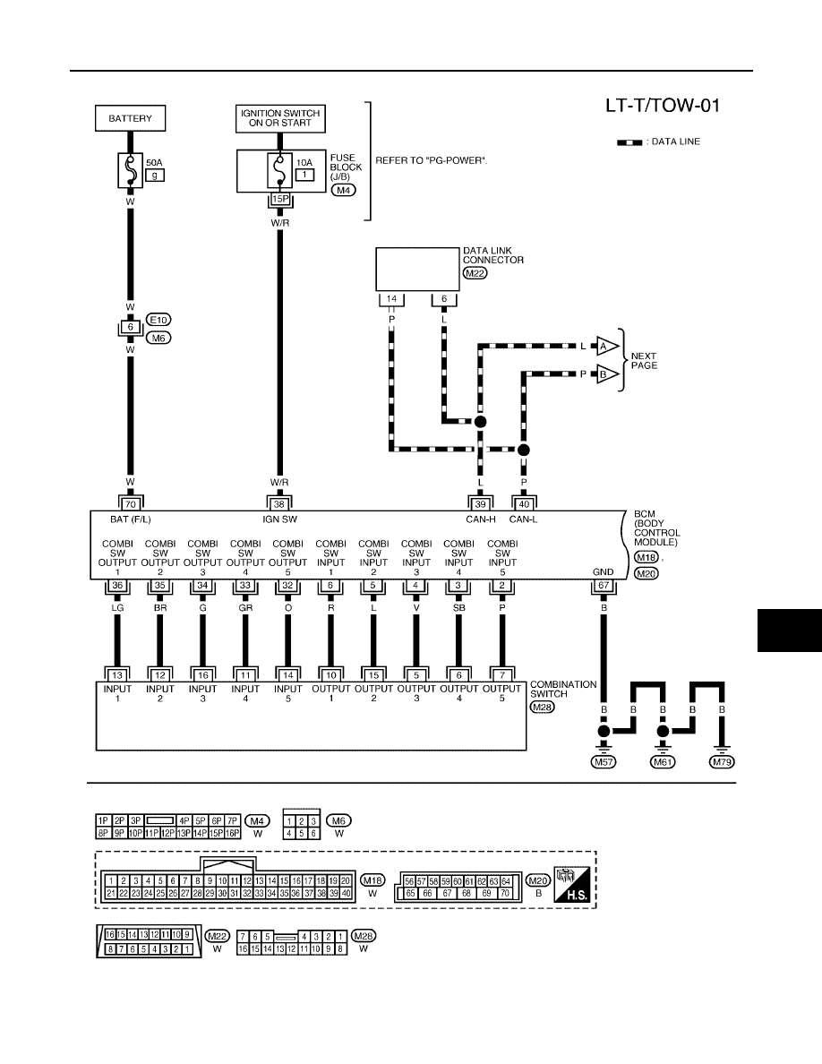
Wiring Diagram — T/TOW —

EKS009MK

WKWA2067E

LT-126

TRAILER TOW

2005 Pathfinder

WKWA2042E

TRAILER TOW

LT-127

C

D

E

F

G

H

I

J

L

M

A

B

LT

2005 Pathfinder

WKWA2043E

LT-128

TRAILER TOW

2005 Pathfinder

WKWA2085E

INTERIOR ROOM LAMP

LT-129

C

D

E

F

G

H

I

J

L

M

A

B

LT

2005 Pathfinder

INTERIOR ROOM LAMP

PFP:26410

Component Parts and Harness Connector Location

EKS009ML

LKIA0562E

LT-130

INTERIOR ROOM LAMP

2005 Pathfinder

System Description

EKS009MM

When room lamp and personal lamp switch is in DOOR position, room lamp and personal lamp ON/OFF is
controlled by timer according to signals from switches including key switch, front door switch LH, unlock signal
from keyfob, door lock and unlock switch, key cylinder switch, ignition switch and glass hatch ajar switch.
When room/map lamp and personal lamp turns ON, there is a gradual brightening over 1 second. When room/
map lamp and personal lamp turns OFF, there is a gradual dimming over 1 second.
The room/map lamp and personal lamp timer is controlled by the BCM (body control module).
Room/map lamp and personal lamp timer control settings can be changed with CONSULT-II.
Ignition keyhole illumination turns ON when front door LH is opened (door switch ON) or key is removed from
key cylinder. Illumination turns OFF when front door LH is closed (door switch OFF).

POWER SUPPLY AND GROUND

Power is supplied at all times

through 10A fuse (No. 25, located in the fuse and fusible link box)

to key switch terminal 2, and

through 10A fuse [No. 18, located in the fuse block (J/B)]

to BCM terminal 57, and

through 50A fusible link (letter , located in the fuse and fusible link box)

to BCM terminal 70.

When the key is inserted in key switch, power is supplied

through the key switch terminal 1

to BCM terminal 37.

With the ignition switch in the ON or START position, power is supplied

through 10A fuse [No. 1, located in the fuse block (J/B)]

to BCM terminal 38.

Ground is supplied

to BCM terminal 67

through grounds M57, M61 and M79.

When the front door LH is opened, ground is supplied

to BCM terminal 47

through front door switch LH terminal 2

through case ground of front door switch LH.

When the front door RH is opened, ground is supplied

to BCM terminal 12

through front door switch RH terminal 2

through case ground of front door switch RH.

When the rear door LH is opened, ground is supplied

to BCM terminal 48

through rear door switch LH terminal 2

through case ground of rear door switch LH.

When the rear door RH is opened, ground is supplied

to BCM terminal 13

through rear door switch RH terminal 2

through case ground of rear door switch RH.

When the glass hatch is opened, ground is supplied

to BCM terminal 42

through glass hatch ajar switch terminal 1

through case ground of glass hatch ajar switch.

When the liftgate is opened, ground is supplied

to BCM terminal 43

through back door switch terminal 3

INTERIOR ROOM LAMP

LT-131

C

D

E

F

G

H

I

J

L

M

A

B

LT

2005 Pathfinder

through back door switch terminal 1

through grounds D406 and D504.

When the front door LH or RH is unlocked by the door lock and unlock switch, BCM receives ground signal

to BCM terminal 46

through main power window and door lock/unlock switch terminal 11 or power window and door lock/
unlock switch RH terminal 2

through main power window and door lock/unlock switch terminal 14 or power window and door lock/
unlock switch RH terminal 3

through grounds M57, M61 and M79.

When the front door LH is unlocked by the key, the BCM receives ground signal

to BCM terminal 7

through front door lock assembly LH (key cylinder switch) terminal 3

through front door lock assembly LH (key cylinder switch) terminal 4

through grounds M57, M61 and M79.

When a signal, or combination of signals is received by BCM, ground is supplied

to front room/map lamp assembly terminal 2

to personal lamp 2nd row terminal 2 (with rear map lamps)

to room lamp 2nd row terminal 1 (without map lamps)

through BCM terminal 63, and

to cargo lamp terminal 1

through BCM terminal 49.

With power and ground supplied, the lamps illuminate.

SWITCH OPERATION

When any door switch is ON (door is opened), ground is supplied

to front room/map lamp assembly terminal 2

to personal lamp 2nd row terminal 2 (with rear map lamps)

to room lamp 2nd row terminal 1 (without map lamps)

through BCM terminal 63, and

to ignition keyhole illumination terminal 2

through BCM terminal 1.

And power is supplied

through BCM terminal 56

to ignition keyhole illumination terminal 1

to front room/map lamp assembly terminal 1

to vanity lamp LH and RH terminal 1

to personal lamp 2nd row terminal 1 (with rear map lamps)

to room lamp 2nd row terminal 2 (without map lamps)

to cargo lamp terminal 2.

When map lamp switch is ON, ground is supplied

to front room/map lamp assembly terminal 3

through grounds M57, M61 and M79.

When vanity lamp (LH and RH) is ON, ground is supplied

to vanity lamp (LH and RH) terminal 2

through grounds B7 and B19.

When personal lamp 2nd row (with rear map lamps) is ON, ground is supplied

to personal lamp 2nd row terminal 3 (with rear map lamps)

through grounds M57, M61 and M79.

When room lamp 2nd row (without map lamps) is ON, ground is supplied through room lamp case ground.
When cargo lamp is ON, ground is supplied through cargo lamp case ground.

LT-132

INTERIOR ROOM LAMP

2005 Pathfinder

ROOM LAMP TIMER OPERATION

When lamp switch is in DOOR position, and when all conditions below are met, BCM performs timer control
(maximum 30 seconds) for interior room lamp and map lamp ON/OFF.
Power is supplied

through 10A fuse [No. 25, located in the fuse block (J/B)]

to key switch terminal 2.

Key is removed from ignition key cylinder (key switch OFF), power will not be supplied to BCM terminal 37.
Ground is supplied

to BCM terminal 46

through main power window and door lock/unlock switch terminal 11.

At the time that front door LH is opened, BCM detects that front door LH is unlocked. It determines that interior
room lamp and map lamp timer operation conditions are met, and turns the interior room lamps ON for 30 sec-
onds.
Key is in ignition key cylinder (key switch ON), power is supplied

through key switch terminal 1

to BCM terminal 37.

When key is removed from key switch and key lock solenoid (key switch OFF), power supply to BCM terminal
37 is terminated. BCM detects that key has been removed, determines that interior room lamp and map lamp
timer conditions are met, and turns the interior room lamps ON for 30 seconds.
When front door LH opens

closes, and the key is not inserted in the key switch (key switch OFF), BCM ter-

minal 47 changes between 0V (door open)

12V (door closed). The BCM determines that conditions for inte-

rior room lamp operation are met and turns the interior room lamp ON for 30 seconds.
Timer control is canceled under the following conditions.

Front door LH is locked [when locked by keyfob, main power window and door lock/unlock switch, or front
door lock assembly LH (key cylinder switch)]

Front door LH is opened (front door switch LH turns ON)

Ignition switch ON.

INTERIOR LAMP BATTERY SAVER CONTROL

If interior lamp is left ON, it will not be turned off even when door is closed.
BCM turns off interior lamp automatically to save battery 30 minutes after ignition switch is turned off.
BCM controls interior lamps listed below:

Vanity lamp

Front room/map lamp

Cargo lamp

Personal lamp 2nd row (with rear map lamps)

Room lamp 2nd row (without map lamps)

Ignition keyhole illumination

After lamps turn OFF by the battery saver system, the lamps illuminate again when

signal received from keyfob, main power window and door lock/unlock switch or front door lock assembly
LH (key cylinder switch) is locked or unlocked

door is opened or closed

key is removed from ignition key cylinder or inserted in ignition key cylinder.

Interior lamp battery saver control period can be changed by the function setting of CONSULT-II.


Content      ..     338      339      340      341     ..