Nissan Pathfinder (2005 year). Manual - part 170
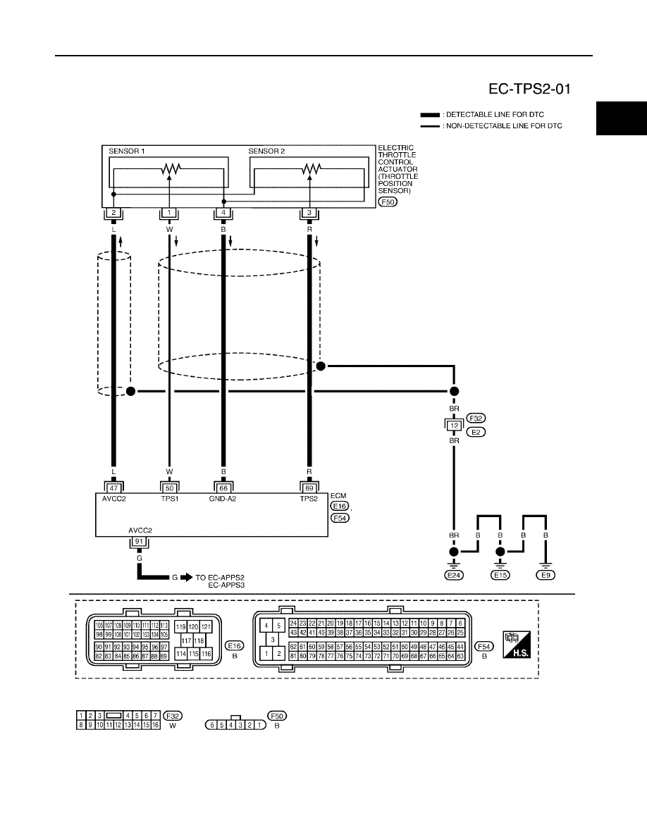
DTC P0122, P0123 TP SENSOR
EC-211
C
D
E
F
G
H
I
J
K
L
M
A
EC
2005 Pathfinder
Wiring Diagram
UBS00K68
BBWA1745E
|
|
|
DTC P0122, P0123 TP SENSOR EC-211 C D E F G H I J K L M A EC
2005 Pathfinder Wiring Diagram UBS00K68 BBWA1745E |