Nissan Pathfinder (2005 year). Manual - part 169
DTC P0112, P0113 IAT SENSOR
EC-203
C
D
E
F
G
H
I
J
K
L
M
A
EC
2005 Pathfinder
4.
CHECK INTAKE AIR TEMPERATURE SENSOR
Refer to
EC-203, "Component Inspection"
.
OK or NG
OK
>> GO TO 5.
NG
>> Replace mass air flow sensor (with intake air temperature sensor).
5.
CHECK INTERMITTENT INCIDENT
Refer to
EC-158, "TROUBLE DIAGNOSIS FOR INTERMITTENT INCIDENT"
.
>> INSPECTION END
Component Inspection
UBS00K5V
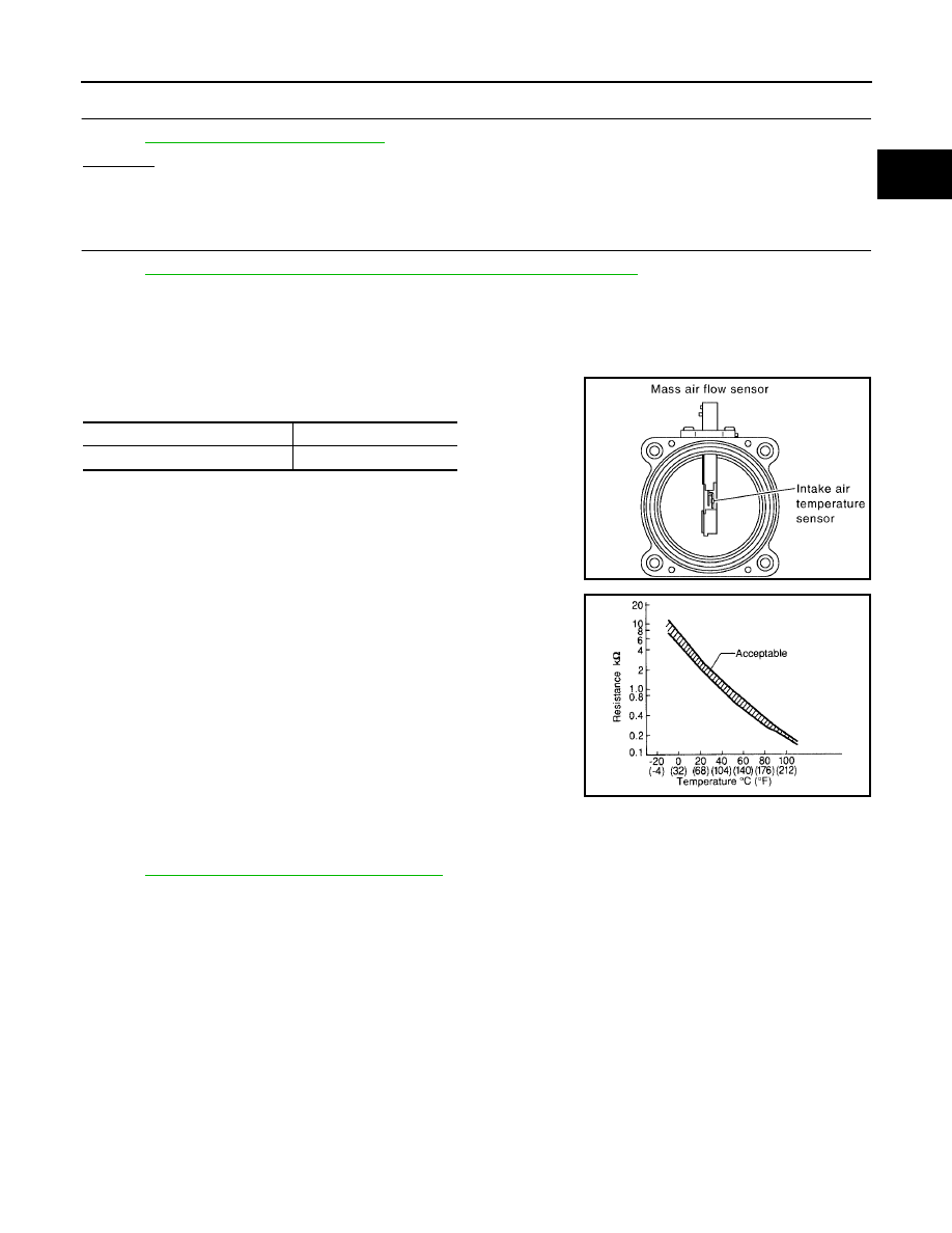
INTAKE AIR TEMPERATURE SENSOR
1.
Check resistance between mass air flow sensor terminals 5 and
6 under the following conditions.
2.
If NG, replace mass air flow sensor (with intake air temperature
sensor).
Removal and Installation
UBS00K5W
MASS AIR FLOW SENSOR
Refer to
EM-15, "AIR CLEANER AND AIR DUCT"
.
Intake air temperature
°
C (
°
F)
Resistance k
Ω
25 (77)
1.94 - 2.06
PBIB1604E
SEF012P