Nissan Pathfinder (2005 year). Manual - part 165
DTC P0011, P0021 IVT CONTROL
EC-171
C
D
E
F
G
H
I
J
K
L
M
A
EC
2005 Pathfinder
On Board Diagnosis Logic
UBS00K4W
FAIL-SAFE MODE
When the malfunction is detected, the ECM enters fail-safe mode.
DTC Confirmation Procedure
UBS00K4X
CAUTION:
Always drive at a safe speed.
NOTE:
●
If DTC P0011 or P0021 is displayed with DTC P1111 or P1136, first perform trouble diagnosis for
DTC P1111 or P1136. Refer to
.
●
If DTC Confirmation Procedure has been previously conducted, always turn ignition switch OFF and wait
at least 10 seconds before conducting the next test.
TESTING CONDITION:
Before performing the following procedure, confirm that battery voltage is between 10V and 16V at
idle.
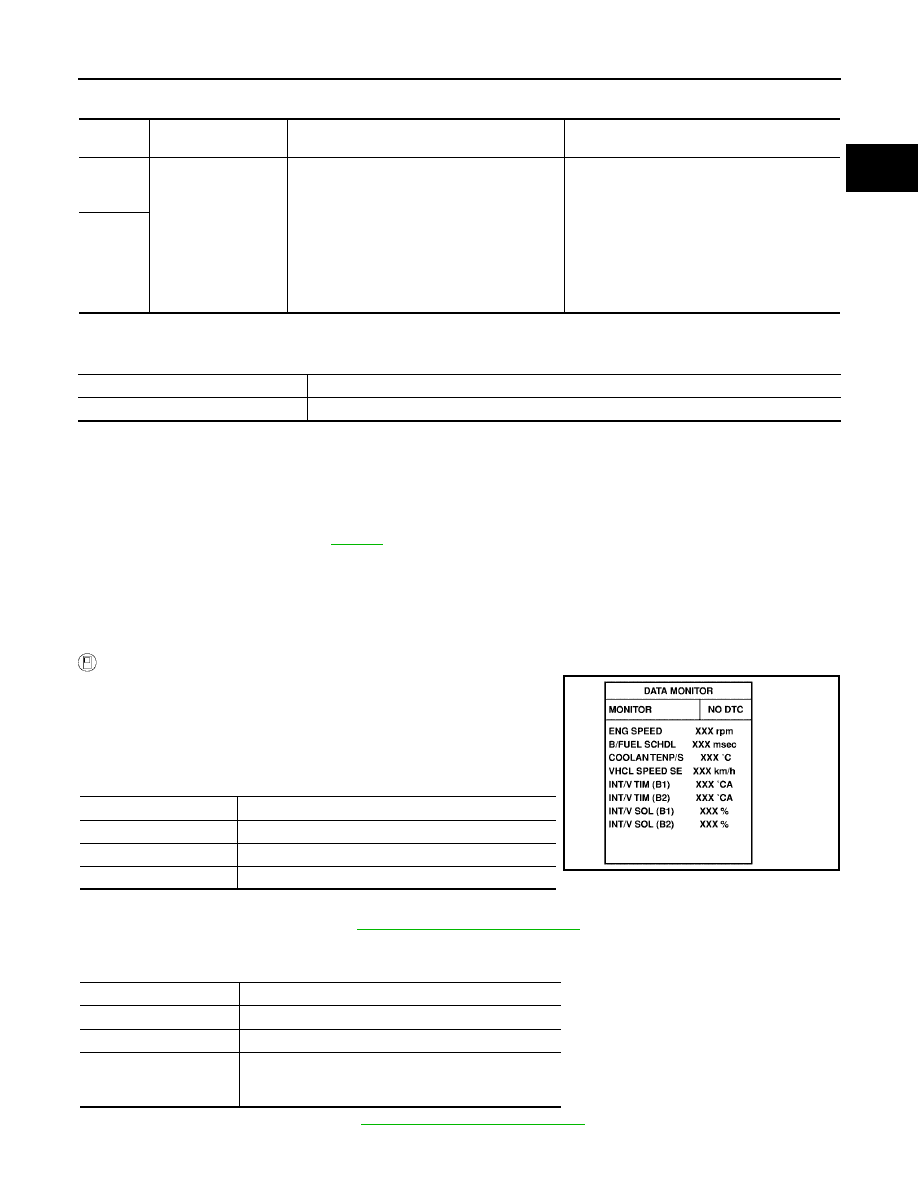
WITH CONSULT-II
1.
Turn ignition switch ON and select “DATA MONITOR” mode with
CONSULT-II.
2.
Start engine and warm it up to the normal operating tempera-
ture.
3.
Maintain the following conditions for at least 6 consecutive sec-
onds. Hold the accelerator pedal as steady as possible.
4.
Stop vehicle with engine running and let engine idle for 10 seconds.
5.
If the 1st trip DTC is detected, go to
EC-172, "Diagnostic Procedure"
.
If the 1st trip DTC is not detected, go to next step.
6.
Maintain the following conditions for at least 20 consecutive seconds.
7.
If the 1st trip DTC is detected, go to
EC-172, "Diagnostic Procedure"
.
DTC No.
Trouble diagnosis
name
Detecting condition
Possible cause
P0011
0011
(Bank 1)
Intake valve timing
control performance
There is a gap between angle of target and
phase-control angle degree.
●
Crankshaft position sensor (POS)
●
Camshaft position sensor (PHASE)
●
Intake valve timing control solenoid valve
●
Accumulation of debris to the signal pick-up
portion of the camshaft
●
Timing chain installation
●
Foreign matter caught in the oil groove for
intake valve timing control
P0021
0021
(Bank 2)
Detected items
Engine operating condition in fail-safe mode
Intake valve timing control
The signal is not energized to the solenoid valve and the valve control does not function.
ENG SPEED
1,200 - 2,000 rpm
COOLAN TEMP/S
60 - 120
°
C (140 - 248
°
F)
B/FUEL SCHDL
More than 3.5 msec
Selector lever
P or N position
ENG SPEED
1,700 - 3,175 rpm (A constant rotation is maintained.)
COOLAN TEMP/S
70 - 105
°
C (158 - 221
°
F)
Selector lever
1st or 2nd position
Driving location uphill
Driving vehicle uphill
(Increased engine load will help maintain the driving
conditions required for this test.)
SEF353Z