Nissan Pathfinder (2005 year). Manual - part 142


  Index      Manuals     Nissan Pathfinder (2005 year) - Service and Repair Manual


Search            copyright infringement  


Content      ..     140      141      142      143     ..


Nissan Pathfinder (2005 year). Manual - part 142


WARNING CHIME

DI-53

C

D

E

F

G

H

I

J

L

M

A

B

DI

2005 Pathfinder

2.

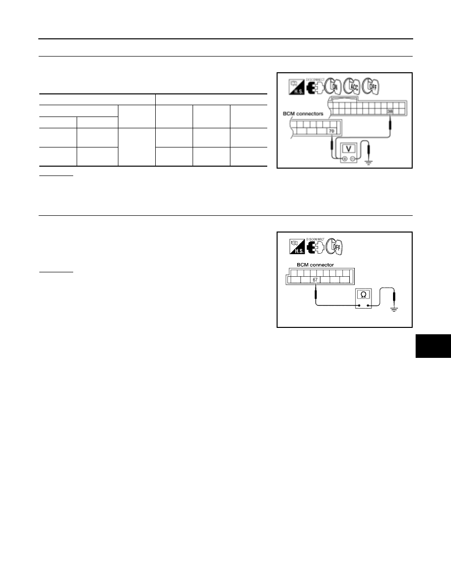
CHECK POWER SUPPLY CIRCUIT

1.

Disconnect BCM connectors M18 and M20.

2.

Check voltage between BCM harness connector terminals and
ground.

OK or NG

OK

>> GO TO 3.

NG

>> Check harness for open between BCM and fuse.

3.

CHECK GROUND CIRCUIT

1.

Turn ignition switch OFF.

2.

Check continuity between BCM harness connector M20 terminal
67 and ground.

OK or NG

OK

>> Inspection End.

NG

>> Repair harness or connector.

Terminals

Ignition switch position

(+)

(–)

OFF

ACC

ON

Connector

Terminal

M20

70

Ground

Battery
voltage

Battery
voltage

Battery
voltage

M18

38

0V

0V

Battery
voltage

WKIA1513E

Continuity should exist.

WKIA1514E

DI-54

WARNING CHIME

2005 Pathfinder

CONSULT-II Function (BCM)

EKS009OB

CONSULT-II can display each diagnostic item using the diagnostic test modes shown following.

CONSULT-II BASIC OPERATION PROCEDURE

CAUTION:

If CONSULT-II is used with no connection of CONSULT-II CONVERTER, malfunctions might be
detected in self-diagnosis depending on control unit which carries out CAN communication.

1.

With the ignition switch OFF, connect CONSULT-II and CON-
SULT-II CONVERTER to the data link connector, and turn igni-
tion switch ON.

2.

Touch “START (NISSAN BASED VHCL)”.

3.

Touch “BCM” on “SELECT SYSTEM” screen. If “BCM” is not
indicated, go to

BCS-11, "CONSULT–II INSPECTION PROCE-

DURE"

.

BCM

diagnostic test item

Diagnostic mode

Description

Inspection by part

WORK SUPPORT

Supports inspections and adjustments. Commands are transmitted to the BCM
for setting the status suitable for required operation, input/output signals are
received from the BCM and received data is displayed.

DATA MONITOR

Displays BCM input/output data in real time.

ACTIVE TEST

Operation of electrical loads can be checked by sending drive signal to them.

SELF-DIAG RESULTS

Displays BCM self-diagnosis results.

CAN DIAG SUPPORT MNTR

The result of transmit/receive diagnosis of CAN communication can be read.

ECU PART NUMBER

BCM part number can be read.

CONFIGURATION

Performs BCM configuration read/write functions.

BBIA0538E

BCIA0029E

BCIA0030E

WARNING CHIME

DI-55

C

D

E

F

G

H

I

J

L

M

A

B

DI

2005 Pathfinder

4.

Touch “BUZZER” or “BCM”.

5.

Select “DATA MONITOR” or “SELF-DIAG RESULTS”.

DATA MONITOR
Operation Procedure

1.

Touch “BUZZER” on “SELECT TEST ITEM” screen.

2.

Touch “DATA MONITOR” on “SELECT DIAG MODE” screen.

3.

Touch “ALL SIGNALS” or “SELECTION FROM MENU” on “DATA MONITOR“ screen.

4.

If “SELECTION FROM MENU” is selected, touch the item you desire to monitor. If “ALL SIGNALS” is
selected, all control items are monitored.

5.

Touch “START”.

6.

During monitoring, touching “RECORD” can start recording the monitored item status.

Display Item List

ACTIVE TEST
Operation Procedure

1.

Touch “BUZZER” on “SELECT TEST ITEM” screen.

2.

Touch “ACTIVE TEST” on “SELECT DIAG MODE” screen.

3.

Touch the item to be tested, and check the operation.

4.

During the operation check, touching “OFF” deactivates the operation.

SKIA5788E

BCIA0031E

ALL SIGNALS

Monitors main items.

SELECTION FROM MENU

Selects and monitors items.

Monitored item

Description

IGN ON SW

Indicates [ON/OFF] condition of ignition switch.

KEY ON SW

Indicates [ON/OFF] condition of key switch.

DOOR SW-DR

Indicates [ON/OFF] condition of front door switch (driver side).

LIGHT SW 1ST

Indicates [ON/OFF] condition of lighting switch.

BUCKLE SW

Indicates [ON/OFF] condition of seat belt buckle switch LH.

DI-56

WARNING CHIME

2005 Pathfinder

Display Item List

SELF-DIAGNOSTIC RESULTS
Operation Procedure

1.

Touch "BCM" on "SELECT TEST ITEM" screen.

2.

Touch "SELF-DIAG RESULTS" on "SELECT DIAG MODE" screen.

3.

Self-diagnostic results are displayed.

Display Item List

NOTE:
If "CAN communication [U1000]" is indicated, after printing the monitor item, go to "CAN System". Refer to

LAN-24, "CAN COMMUNICATION"

.

All Warning Chimes Do Not Operate

EKS009OC

1.

CHECK BCM CHIME OPERATION

Select "BUZZER" on CONSULT-II, and perform "LIGHT WARN
ALM", "IGN KEY WARN ALM", OR "SEAT BELT WARN TEST"
active test.

Does chime sound?

YES

>> Replace the BCM. Refer to

BCS-19, "Removal and

Installation of BCM"

.

NO

>> Replace

the

combination

meter.

Refer

to

DI-26,

"Removal and Installation of Combination Meter"

.

Test item

Malfunction is detected when···

LIGHT WARN ALM

This test is able to check light warning chime operation. Light warning chime sounds for 2 sec-
onds after touching “ON” on CONSULT-II screen.

IGN KEY WARN ALM

This test is able to check key warning chime operation. Key warning chime sounds for 2 seconds
after touching “ON” on CONSULT-II screen.

SEAT BELT WARN TEST

This test is able to check seat belt warning chime operation. Seat belt warning chime sounds for 2
seconds after touching “ON” on CONSULT-II screen.

Monitored Item

CONSULT-II display

Description

CAN communication

CAN communication [U1000]

Malfunction is detected in CAN communication.

SKIA6331E

WARNING CHIME

DI-57

C

D

E

F

G

H

I

J

L

M

A

B

DI

2005 Pathfinder

Key Warning Chime and Light Warning Chime Do Not Operate (Seat Belt Warn-
ing Chime Does Operate)

EKS009OD

1.

CHECK BCM INPUT SIGNAL

With CONSULT-II

1.

Select "BCM" on CONSULT-II.

2.

With "DATA MONITOR" of "BUZZER", confirm "DOOR SW-DR"
changes with the status of front door LH.

Without CONSULT-II

Check voltage between BCM harness connector M19 terminal 47
and ground.

OK or NG

OK

>> Replace the BCM. Refer to

BCS-19, "Removal and

Installation of BCM"

.

NG

>> GO TO 2.

2.

CHECK FRONT DOOR SWITCH LH CIRCUIT

1.

Turn ignition switch OFF.

2.

Disconnect BCM connector M19 and front door switch LH connector B8.

3.

Check continuity between BCM harness connector M19 terminal
47 and front door switch LH harness connector B8 terminal 2.

4.

Check continuity between BCM harness connector M19 terminal
47 and ground.

OK or NG

OK

>> GO TO 3.

NG

>> Repair harness or connector.

When front door LH is
opened

: DOOR SW-DR ON

When front door LH is
closed

: DOOR SW-DR OFF

LKIA0335E

When front door LH is
opened

: Approx. 0V

When front door LH is
closed

: Approx. 5V

WKIA1515E

Continuity should exist.

Continuity should not exist.

WKIA1516E

DI-58

WARNING CHIME

2005 Pathfinder

3.

CHECK FRONT DOOR SWITCH LH

Check continuity between front door switch LH terminal 2 and
exposed metal of switch while pressing and releasing switch.

OK or NG

OK

>> Replace the BCM. Refer to

BCS-19, "Removal and

Installation of BCM"

.

NG

>> Replace the front door switch LH.

Key Warning Chime Does Not Operate

EKS009OE

1.

CHECK FUSE

Check if the key switch fuse (No. 25, located in the fuse and fusible link box) is blown. Refer to

DI-49, "Wiring

Diagram — CHIME —"

.

Is the fuse blown?

YES

>> Replace the fuse. Be sure to repair the cause of malfunction before installing new fuse.

NO

>> GO TO 2.

2.

CHECK WARNING CHIME OPERATION

With key removed from the ignition and the front door LH open, turn the lighting switch to 1st or 2nd position.

Does warning chime sound?

YES

>> GO TO 3.

NO

>> Go to

DI-56, "All Warning Chimes Do Not Operate"

or

DI-57, "Key Warning Chime and Light

Warning Chime Do Not Operate (Seat Belt Warning Chime Does Operate)"

.

When front door switch
LH is released

: Continuity should exist.

When front door switch
LH is pushed

: Continuity should not
exist.

WKIA2023E

WARNING CHIME

DI-59

C

D

E

F

G

H

I

J

L

M

A

B

DI

2005 Pathfinder

3.

CHECK BCM INPUT SIGNAL

With CONSULT-II

With "DATA MONITOR" of "BUZZER", confirm "KEY ON SW"
changes when the key is inserted/removed from the ignition key cyl-
inder.

Without CONSULT-II

Check voltage between BCM harness connector M18 terminal 37
and ground.

OK or NG

OK

>> Replace the BCM. Refer to

BCS-19, "Removal and

Installation of BCM"

.

NG

>> GO TO 4.

4.

CHECK KEY SWITCH

1.

Turn ignition switch OFF.

2.

Disconnect key switch and key lock solenoid connector M27.

3.

Check continuity between key switch and key lock solenoid ter-
minals 1 and 2.

OK or NG

OK

>> GO TO 5.

NG

>> Replace the key switch and key lock solenoid.

When key is inserted in ignition
key cylinder

: KEY ON SW ON

When key is removed from
ignition key cylinder

: KEY ON SW OFF

SKIA1960E

Terminals

Condition

Voltage (V)

(+)

(–)

Connector

Terminal

M18

37

Ground

Key is inserted

Battery voltage

Key is removed

0V

LKIA0255E

Terminals

Condition

Continuity

1

2

Key is inserted

Yes

Key is removed

No

WKIA3291E

DI-60

WARNING CHIME

2005 Pathfinder

5.

CHECK KEY SWITCH CIRCUIT

1.

Disconnect BCM connector M18.

2.

Check continuity between BCM harness connector M18 terminal
37 and key switch and key lock solenoid harness connector M27
terminal 1.

3.

Check continuity between BCM harness connector M18 terminal
37 and ground.

OK or NG

OK

>> GO TO 6.

NG

>> Repair harness or connector.

6.

CHECK KEY SWITCH POWER SUPPLY CIRCUIT

Check voltage between key switch and key lock solenoid harness
connector M27 terminal 2 and ground.

OK or NG

OK

>> Replace the BCM. Refer to

BCS-19, "Removal and

Installation of BCM"

.

NG

>> Check harness for open between fuse and key switch

and key lock solenoid.

Light Warning Chime Does Not Operate

EKS009OF

1.

CHECK WARNING CHIME OPERATION

Check key warning chime and seat belt warning chime functions.

Do key warning chime and seat belt warning chime sound?

YES

>> GO TO 2.

NO

>> Go to

DI-56, "All Warning Chimes Do Not Operate"

.

2.

CHECK BCM INPUT SIGNAL

With CONSULT-II

1.

Select "BCM".

2.

With "DATA MONITOR" of "BUZZER", confirm "LIGHT SW 1ST"
status changes when the lighting switch is moved from ON (1st
position) to OFF.

Without CONSULT-II

Check combination switch. Refer to

LT-92, "Combination Switch

Reading Function"

.

OK or NG

OK

>> Replace the BCM. Refer to

BCS-19, "Removal and

Installation of BCM"

.

NG

>> Check lighting switch. Refer to

LT-92, "Combination Switch Reading Function"

.

Continuity should exist.

Continuity should not exist.

WKIA3292E

Battery voltage should exist.

WKIA3293E

Lighting switch ON (1st position)

: LIGHT SW 1ST ON

Lighting switch OFF

: LIGHT SW 1ST OFF

WKIA1877E


Content      ..     140      141      142      143     ..