Nissan Pathfinder (2005 year). Manual - part 74
DVD ENTERTAINMENT SYSTEM
AV-67
C
D
E
F
G
H
I
J
L
M
A
B
AV
2005 Pathfinder
Power Supply Circuit Inspection
EKS009V4
1.
CHECK FUSES
Check that the following fuses are not blown.
OK or NG
OK
>> GO TO 2.
NG
>> If fuse is blown, be sure to eliminate cause of problem before installing new fuse. Refer to
"POWER SUPPLY ROUTING CIRCUIT"
.
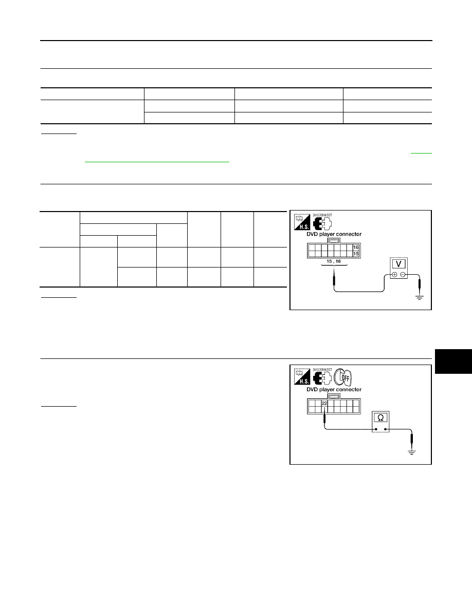
2.
POWER SUPPLY CIRCUIT CHECK
1.
Disconnect DVD player connector M205.
2.
Check voltage between the DVD player and ground.
OK or NG
OK
>> GO TO 3.
NG
>>
●
Check connector housings for disconnected or loose
terminals.
●
Repair harness or connector.
3.
GROUND CIRCUIT CHECK
Check continuity between DVD player harness connector M206 ter-
minal 22 and ground.
OK or NG
OK
>> Inspection End.
NG
>>
●
Check connector housings for disconnected or loose
terminals.
●
Repair harness or connector.
Unit
Terminals
Signal name
Fuse No.
DVD player
16
Battery power
29
15
Ignition switch ACC or ON
4
Unit
Terminal No.
OFF
ACC
ON
(+)
(-)
Connector
Terminal
DVD player
M205
16
Ground
Battery
voltage
Battery
voltage
Battery
voltage
15
Ground
0V
Battery
voltage
Battery
voltage
WKIA1197E
Continuity should exist.
WKIA1198E