Nissan Pathfinder (2005 year). Manual - part 51


  Index      Manuals     Nissan Pathfinder (2005 year) - Service and Repair Manual


Search            copyright infringement  


Content      ..     49      50      51      52     ..


Nissan Pathfinder (2005 year). Manual - part 51


TROUBLE DIAGNOSIS

ATC-55

C

D

E

F

G

H

I

K

L

M

A

B

ATC

2005 Pathfinder

Operational Check (Rear)

EJS002X1

The purpose of the operational check is to confirm that the system operates properly.
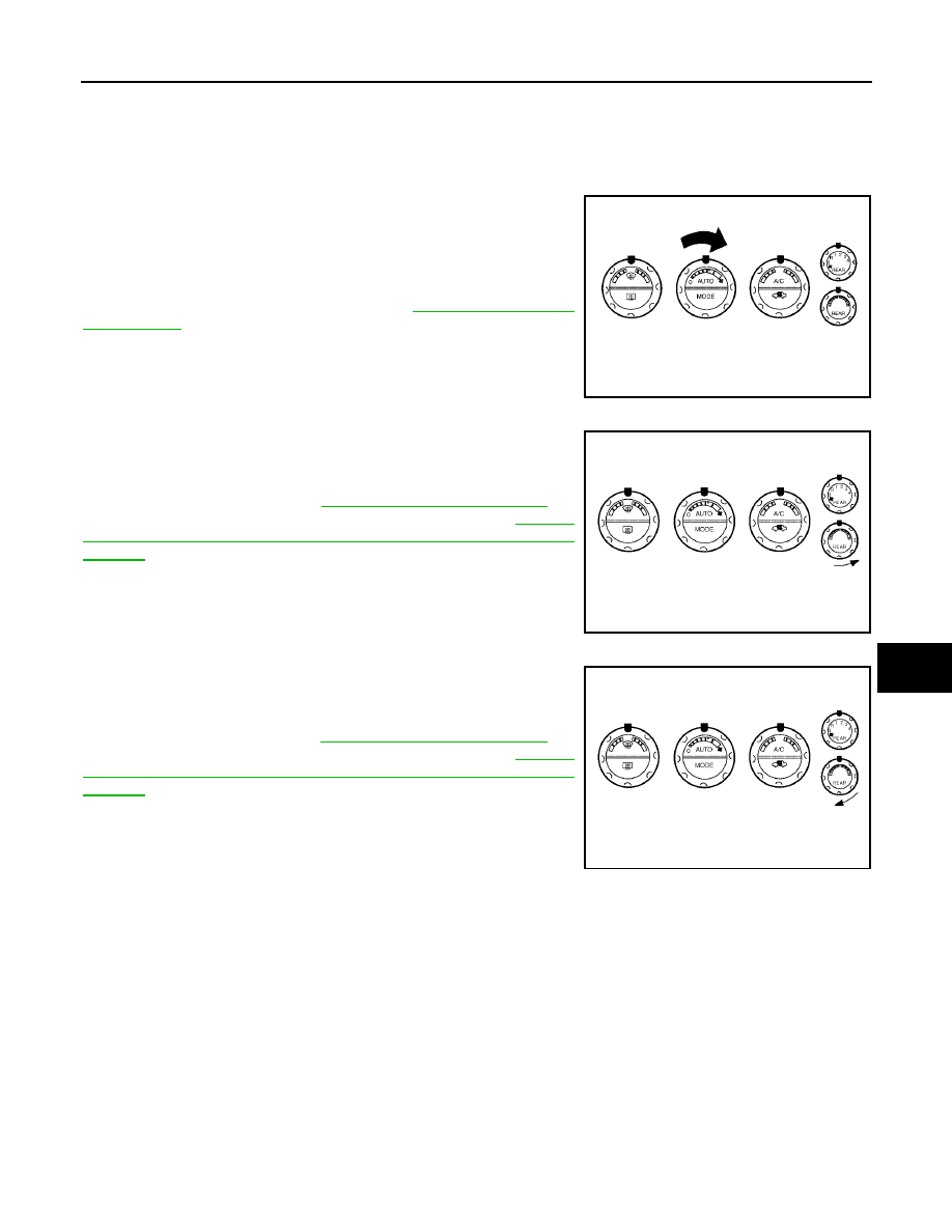
CHECKING BLOWER

1.

Turn the rear blower control dial counterclockwise to switch
position "1". Fan should operate on low speed.

2.

Turn the rear blower control dial clockwise to switch positions
"2", "3", and "4" until all speeds are checked.

3.

Leave fan on MAX speed.

If NG, go to trouble diagnosis procedure for

ATC-82, "Rear Blower

Motor Circuit"

.

If OK, continue the check.

CHECKING TEMPERATURE DECREASE

1.

Rotate temperature and mode dial fully counterclockwise.

2.

Check for cold air at appropriate discharge air outlets.

If NG, listen for sound of air mix door motor operation. If OK, go to
trouble diagnosis procedure for

ATC-102, "Insufficient Cooling"

. If

air mix door motor appears to be malfunctioning, go to

ATC-69,

"DIAGNOSTIC PROCEDURE FOR AIR MIX DOOR MOTOR
(REAR)"

.

If OK, continue the check.

CHECKING TEMPERATURE INCREASE

1.

Rotate temperature and mode dial clockwise.

2.

Check for hot air at appropriate discharge air outlets.

If NG, listen for sound of air mix door motor operation. If OK, go to
trouble diagnosis procedure for

ATC-109, "Insufficient Heating"

. If

air mix door motor appears to be malfunctioning, go to

ATC-69,

"DIAGNOSTIC PROCEDURE FOR AIR MIX DOOR MOTOR
(REAR)"

.

If OK, continue the check.

Conditions

: Engine running and at normal operating temperature

WJIA1068E

WJIA1069E

WJIA1070E

ATC-56

TROUBLE DIAGNOSIS

2005 Pathfinder

Power Supply and Ground Circuit for Front Air Control

EJS002X2

SYMPTOM: A/C system does not come on.

INSPECTION FLOW

*1

ATC-56, "Power Supply and Ground
Circuit for Front Air Control"

.

*2

ATC-52, "Operational Check (Front)"

or

ATC-55, "Operational Check

(Rear)"

.

WJIA1439E

TROUBLE DIAGNOSIS

ATC-57

C

D

E

F

G

H

I

K

L

M

A

B

ATC

2005 Pathfinder

COMPONENT DESCRIPTION
Front Air Control

The front air control has a built-in microcomputer which processes
information sent from various sensors needed for air conditioner
operation. The air mix door motors, mode door motor, intake door
motor, blower motor and compressor are then controlled.
The front air control is unitized with control mechanisms. When the
various switches and temperature dials are operated, data is input to
the front air control.
Self-diagnostic functions are also built into the front air control to pro-
vide quick check of malfunctions in the auto air conditioner system.

Potentio Temperature Control (PTC)

There are two PTCs (passenger and driver) built into the front air
control. They can be set at an interval of 0.5

°

C (1.0

°

F) in the 16

°

C

(60

°

F) to 32

°

C (90

°

F) temperature range by rotating the temperature

dial. The set temperature is displayed.

DIAGNOSTIC PROCEDURE FOR A/C SYSTEM

SYMPTOM: A/C system does not come on.

WJIA1075E

WJIA1050E

WJIA1461E

ATC-58

TROUBLE DIAGNOSIS

2005 Pathfinder

1.

CHECK POWER SUPPLY CIRCUITS FOR FRONT AIR CONTROL

1.

Disconnect front air control connector.

2.

Check voltage between front air control harness connector M49
terminals 6 and 19, and ground.

OK or NG

OK

>> GO TO 2.

NG

>> Check 10A fuses [Nos. 8 and 19, located in the fuse block (J/B)]. Refer to

PG-79

.

If fuses are OK, check harness for open circuit. Repair or replace as necessary.

If fuses are NG, replace fuse and check harness for short circuit. Repair or replace as neces-
sary.

2.

CHECK GROUND CIRCUIT FOR FRONT AIR CONTROL

1.

Turn ignition switch OFF.

2.

Check continuity between front air control harness connector
M49 terminal 20 and ground.

OK or NG

OK

>> Replace front air control. Refer to

ATC-124, "FRONT

AIR CONTROL"

.

NG

>> Repair harness or connector.

Terminals

Ignition switch position

(+)

(-)

OFF

ACC

ON

Front air

control

connector

Terminal No.

M49

6

Ground

Approx. 0V

Approx. 0V

Battery
voltage

M49

19

Battery
voltage

Battery
voltage

Battery
voltage

WJIA1082E

20 - Ground

: Continuity should exist.

WJIA1239E

TROUBLE DIAGNOSIS

ATC-59

C

D

E

F

G

H

I

K

L

M

A

B

ATC

2005 Pathfinder

Mode Door Motor Circuit

EJS002X3

SYMPTOM:

Air outlet does not change.

Mode door motor does not operate normally.

INSPECTION FLOW

*1

ATC-29, "Discharge Air Flow"

.

*2

ATC-52, "Operational Check
(Front)"

.

*3

ATC-50, "A/C System Self-diagnosis
Function"

.

*4

ATC-51, "SELF-DIAGNOSIS CODE
CHART"

.

*5

ATC-61, "DIAGNOSTIC PROCE-
DURE FOR MODE DOOR
MOTOR"

.

*6

ATC-35, "SYMPTOM TABLE"

WJIA1109E

ATC-60

TROUBLE DIAGNOSIS

2005 Pathfinder

SYSTEM DESCRIPTION
Component Parts

Mode door control system components are:

Front air control

Mode door motor

PBR (built into mode door motor)

In-vehicle sensor

Ambient sensor

Optical sensor

Intake sensor

System Operation

The mode door position (vent, B/L, foot, and defrost) is set by the front air control by means of the mode door
motor. When a mode door position is selected on the front air control, voltage is applied to one circuit of the
mode door motor while ground is applied to the other circuit, causing the mode door motor to rotate. The direc-
tion of rotation is determined by which circuit has voltage applied to it, and which one has ground applied to it.
The front air control monitors the mode door position by measuring the voltage signal on the PBR circuit.
In AUTO mode the mode door position is set by the front air control which determines the proper position
based on inputs from the in-vehicle sensor, ambient sensor, optical sensor, intake sensor, and the temperature
selected by the driver or passenger.

Mode Door Control Specification

WJIA1240E

WJIA0434E

TROUBLE DIAGNOSIS

ATC-61

C

D

E

F

G

H

I

K

L

M

A

B

ATC

2005 Pathfinder

COMPONENT DESCRIPTION
Mode Door Motor

The mode door motor is attached to the heater & cooling unit. It
rotates so that air is discharged from the outlet as indicated by the
front air control. Motor rotation is conveyed to a link which activates
the mode door.

DIAGNOSTIC PROCEDURE FOR MODE DOOR MOTOR

1.

CHECK RESULT FROM FRONT AIR CONTROL SELF-DIAGNOSIS

Self-diagnosis code 92 is present. Refer to

ATC-50, "A/C System Self-diagnosis Function"

.

YES or NO

YES

>> GO TO 2.

NO

>> GO TO 3.

2.

CHECK POWER SUPPLY AND GROUND CIRCUITS FOR MODE DOOR MOTOR

1.

Turn ignition switch OFF.

2.

Disconnect front air control connector and mode door motor
connector.

3.

Check continuity between front air control harness connector
M49 terminal 1 and mode door motor harness connector M142
terminal 1 and between front air control harness connector M49
terminal 14 and mode door motor harness connector M142 ter-
minal 6.

OK or NG

OK

>> Replace mode door motor.

NG

>> Repair or replace harness as necessary.

3.

CHECK PBR REFERENCE SIGNAL VOLTAGE

1.

Turn ignition switch OFF.

2.

Disconnect the mode door motor connector.

3.

Turn ignition switch ON.

4.

Check voltage between mode door motor harness connector
M142 terminal 3 and ground.

OK or NG

OK

>> GO TO 5.

NG

>> GO TO 4.

WJIA1084E

1 - 1

: Continuity should exist.

14 - 6

: Continuity should exist.

WJIA1241E

3 - Ground

: Approx. 5V

WJIA1242E

ATC-62

TROUBLE DIAGNOSIS

2005 Pathfinder

4.

CHECK PBR REFERENCE VOLTAGE CIRCUIT BETWEEN MODE DOOR AND FRONT AIR CONTROL

1.

Turn ignition switch OFF.

2.

Disconnect the front air control connector.

3.

Check continuity between mode door motor harness connector
M142 terminal 3 and front air control harness connector M49 ter-
minal 23.

OK or NG

OK

>> Replace front air control. Refer to

ATC-124, "FRONT

AIR CONTROL"

.

NG

>> Repair or replace harness as necessary.

5.

CHECK PBR GROUND REFERENCE CIRCUIT

1.

Turn ignition switch OFF.

2.

Disconnect the front air control connector.

3.

Check continuity between mode door motor harness connector
M142 terminal 2 and front air control harness connector M49 ter-
minal 26.

OK or NG

OK

>> GO TO 6.

NG

>> Repair or replace harness as necessary.

6.

CHECK PBR FEEDBACK SIGNAL

1.

Reconnect the front air control connector and mode door motor
connector.

2.

Turn ignition switch ON.

3.

Check voltage between front air control harness connector M49
terminal 21 and ground.

4.

Press mode switch through all modes.

OK or NG

OK

>> Replace front air control. Refer to

ATC-124, "FRONT

AIR CONTROL"

.

NG

>> GO TO 7.

7.

CHECK PBR FEEDBACK CIRCUIT

1.

Turn ignition switch OFF.

2.

Disconnect the mode door motor connector and front air control
harness connector.

3.

Check continuity between mode door motor harness connector
M142 terminal 4 and front air control harness connector M49 ter-
minal 21.

OK or NG

OK

>> Replace mode door motor. Refer to

ATC-141, "MODE

DOOR MOTOR"

.

NG

>> Repair or replace harness as necessary.

3 - 23

: Continuity should exist.

WJIA1085E

2 - 26

: Continuity should exist.

WJIA1087E

21 - Ground

: Approx. 0 - 5V

WJIA1088E

4 - 21

: Continuity should exist.

WJIA1089E


Content      ..     49      50      51      52     ..