Nissan Pathfinder (2005 year). Manual - part 44


  Index      Manuals     Nissan Pathfinder (2005 year) - Service and Repair Manual


Search            copyright infringement  


Content      ..     42      43      44      45     ..


Nissan Pathfinder (2005 year). Manual - part 44


SERVICE DATA AND SPECIFICATIONS (SDS)

AT-323

D

E

F

G

H

I

J

K

L

M

A

B

AT

2005 Pathfinder

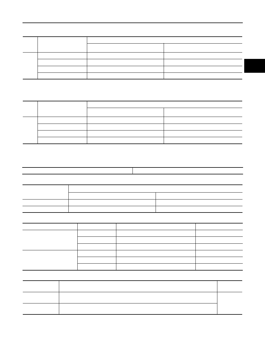
Vehicle Speed at Which Lock-up Occurs/Releases

UCS0038W

2WD MODELS

At closed throttle, the accelerator opening is less than 1/8 condition. (Closed throttle position signal: OFF)

At half throttle, the accelerator opening is 4/8 of the full opening.

4WD MODELS

At closed throttle, the accelerator opening is less than 1/8 condition. (Closed throttle position signal: OFF)

At half throttle, the accelerator opening is 4/8 of the full opening.

Stall Speed

UCS0038Y

Line Pressure

UCS0038Z

A/T Fluid Temperature Sensor

UCS00390

Turbine Revolution Sensor

UCS00391

Final

gear
ratio

Throttle position

Vehicle speed km/h (MPH)

Lock-up “ON”

Lock-up “OFF”

3.133

Closed throttle

78 - 93 (48 - 58)

68 - 82 (42 - 51)

Half throttle

188 - 218 (117 - 135)

147 - 175 (91 - 109)

Closed throttle

78 - 87 (48 - 54)

68 - 76 (42 - 47)

Half throttle

188 - 208 (117 - 129)

147 - 163 (91 - 101)

Final

gear
ratio

Throttle position

Vehicle speed km/h (MPH)

Lock-up “ON”

Lock-up “OFF”

3.357

Closed throttle

73 - 81 (45 - 50)

64 - 72 (40 - 45)

Half throttle

179 - 198 (111 - 123)

140 - 155 (87 - 96)

Closed throttle

78 - 87 (48 - 54)

68 - 76 (42 - 47)

Half throttle

188 - 208 (117 - 129)

147 - 163 (91 - 101)

Stall speed

2,200 - 2,500 rpm

Engine speed

Line pressure [kPa (kg/cm

2

, psi)]

“R” position

“D” position

At idle speed

392 - 441 (4.0 - 4.5, 57 - 64)

373 - 422 (3.8 - 4.3, 54 - 61)

At stall speed

1,700 - 1,890 (17.3 - 19.3, 247 - 274)

1,310 - 1,500 (13.3 - 15.3, 190 - 218)

Name

Condition

CONSULT-II “DATA MONITOR” (Approx.) (V)

Resistance (Approx.) (k

)

A/T fluid temperature sensor 1

0

°

C (32

°

F)

3.2

15

20

°

C (68

°

F)

2.5

6.5

80

°

C (176

°

F)

0.8

0.9

A/T fluid temperature sensor 2

0

°

C (32

°

F)

3.2

10

20

°

C (68

°

F)

2.4

4

80

°

C (176

°

F)

0.65

0.5

Name

Condition

Data

(Approx.)

Turbine revolution
sensor 1

When running at 50 km/h (31 MPH) in 4th speed with the closed throttle position switch “OFF”.

1.3 (kHz)

Turbine revolution
sensor 2

When moving at 20 km/h (12 MPH) in 1st speed with the closed throttle position switch “OFF”.

AT-324

SERVICE DATA AND SPECIFICATIONS (SDS)

2005 Pathfinder

Vehicle Speed Sensor A/T (Revolution Sensor)

UCS00392

Reverse brake

UCS00393

*: Always check with the Parts Department for the latest parts information.

Total End Play

UCS00394

BEARING RACE FOR ADJUSTING TOTAL END PLAY

*: Always check with the Parts Department for the latest parts information.

Name

Condition

Data (Approx.)

Revolution sensor

When moving at 20 km/h (12 MPH).

185 (Hz)

Thickness of retaining plates

Thickness

mm (in)

Part number*

4.2 (0.165)
4.4 (0.173)
4.6 (0.181)
4.8 (0.189)
5.0 (0.197)
5.2 (0.205)

31667 90X14
31667 90X15
31667 90X16
31667 90X17
31667 90X18
31667 90X19

Total end play

mm (in)

0.25 - 0.55 (0.0098 - 0.0217)

Thickness

mm (in)

Part number*

0.8 (0.031)
1.0 (0.039)
1.2 (0.047)
1.4 (0.055)
1.6 (0.063)
1.8 (0.071)

31435 95X00
31435 95X01
31435 95X02
31435 95X03
31435 95X04
31435 95X05

ATC-1

AUTOMATIC AIR CONDITIONER

J AIR CONDITIONER

CONTENTS

C

D

E

F

G

H

I

K

L

M

SECTION

A

B

ATC

2005 Pathfinder

PRECAUTIONS .......................................................... 5

Precautions for Supplemental Restraint System
(SRS) “AIR BAG” and “SEAT BELT PRE-TEN-
SIONER” .................................................................. 5
Precautions for Working with HFC-134a (R-134a)..... 5
Contaminated Refrigerant ........................................ 5
General Refrigerant Precautions .............................. 6
Precautions for Leak Detection Dye ......................... 6
A/C Identification Label ............................................ 7
Precautions for Refrigerant Connection ................... 7

FEATURES OF NEW TYPE REFRIGERANT
CONNECTION ...................................................... 7
O-RING AND REFRIGERANT CONNECTION..... 8

Precautions for Servicing Compressor ....................11
Precautions for Service Equipment .........................11

RECOVERY/RECYCLING EQUIPMENT .............11
ELECTRONIC LEAK DETECTOR .......................11
VACUUM PUMP ................................................. 12
MANIFOLD GAUGE SET .................................... 12
SERVICE HOSES ............................................... 12
SERVICE COUPLERS ........................................ 13
REFRIGERANT WEIGHT SCALE ...................... 13
CHARGING CYLINDER ...................................... 13

Wiring Diagrams and Trouble Diagnosis ................ 13

PREPARATION ......................................................... 14

Special Service Tools ............................................. 14
HFC-134a (R-134a) Service Tools and Equipment... 14
Commercial Service Tools ...................................... 17

REFRIGERATION SYSTEM ..................................... 18

Components ........................................................... 18

FRONT REFRIGERATION SYSTEM .................. 18
REAR REFRIGERATION SYSTEM .................... 19

Refrigerant Cycle ................................................... 20

REFRIGERANT FLOW ....................................... 20
FREEZE PROTECTION ..................................... 20

Refrigerant System Protection ............................... 21

REFRIGERANT PRESSURE SENSOR ............. 21
PRESSURE RELIEF VALVE ............................... 21

LUBRICANT .............................................................. 22

Maintenance of Lubricant Quantity in Compressor... 22

LUBRICANT ........................................................ 22
CHECKING AND ADJUSTING ............................ 22

AIR CONDITIONER CONTROL ............................... 24

Description .............................................................. 24
Operation ................................................................ 24

AIR MIX DOORS CONTROL .............................. 24
BLOWER SPEED CONTROL ............................. 24
INTAKE DOOR CONTROL ................................. 24
MODE DOOR CONTROL ................................... 24
DEFROSTER DOOR CONTROL ........................ 24
MAGNET CLUTCH CONTROL ........................... 25
SELF-DIAGNOSTIC SYSTEM ............................ 25

Description of Control System ................................ 26
Control Operation ................................................... 26

DISPLAY SCREEN .............................................. 27
AUTO SWITCH ................................................... 27
TEMPERATURE CONTROL DIAL (TEMPERA-
TURE CONTROL) (DRIVER SIDE) ..................... 27
TEMPERATURE CONTROL DIAL (TEMPERA-
TURE CONTROL) (PASSENGER SIDE) ............ 27
TEMPERATURE CONTROL DIAL (TEMPERA-
TURE AND MODE CONTROL) (REAR) ............. 27
RECIRCULATION () SWITCH ............................. 27
DEFROSTER (DEF) SWITCH ............................. 27
REAR WINDOW DEFOGGER SWITCH ............. 27
OFF SWITCH ...................................................... 27
A/C SWITCH ....................................................... 27
MODE SWITCH (FRONT) ................................... 27
FRONT BLOWER CONTROL DIAL .................... 27
MODE SWITCH (REAR) ..................................... 27
TEMPERATURE CONTROL DIAL (TEMPERA-
TURE AND MODE CONTROL) ........................... 28
REAR BLOWER CONTROL DIAL ...................... 28

Discharge Air Flow ................................................. 29

FRONT ................................................................ 29
REAR .................................................................. 29

System Description (Front) ..................................... 30

SWITCHES AND THEIR CONTROL FUNCTION... 30

ATC-2

2005 Pathfinder

System Description (Rear) ..................................... 31

SWITCHES AND THEIR CONTROL FUNCTION... 31

CAN Communication System Description .............. 32

TROUBLE DIAGNOSIS ............................................ 33

CONSULT-II Function (BCM) .................................. 33

CONSULT-II BASIC OPERATION ....................... 33
DATA MONITOR .................................................. 34

How to Perform Trouble Diagnosis for Quick and
Accurate Repair ...................................................... 35

WORK FLOW ...................................................... 35
SYMPTOM TABLE .............................................. 35

Component Parts and Harness Connector Location... 36

ENGINE COMPARTMENT .................................. 36
FRONT PASSENGER COMPARTMENT ............ 37
REAR PASSENGER COMPARTMENT ............... 38

Schematic ............................................................... 39
Wiring Diagram —A/C— ......................................... 40
Front Air Control Terminals and Reference Value... 48

PIN CONNECTOR TERMINAL LAYOUT ............ 48
TERMINALS AND REFERENCE VALUE FOR
FRONT AIR CONTROL ....................................... 48

A/C System Self-diagnosis Function ...................... 50

DESCRIPTION .................................................... 50

Operational Check (Front) ...................................... 52

CHECKING MEMORY FUNCTION ..................... 52
CHECKING BLOWER ......................................... 52
CHECKING DISCHARGE AIR ............................ 53
CHECKING RECIRCULATION ............................ 53
CHECKING TEMPERATURE DECREASE ......... 53
CHECKING TEMPERATURE INCREASE .......... 54
CHECK A/C SWITCH .......................................... 54
CHECKING AUTO MODE ................................... 54

Operational Check (Rear) ....................................... 55

CHECKING BLOWER ......................................... 55
CHECKING TEMPERATURE DECREASE ......... 55
CHECKING TEMPERATURE INCREASE .......... 55

Power Supply and Ground Circuit for Front Air Con-
trol ........................................................................... 56

INSPECTION FLOW ........................................... 56
COMPONENT DESCRIPTION ............................ 57
DIAGNOSTIC PROCEDURE FOR A/C SYSTEM... 57

Mode Door Motor Circuit ........................................ 59

INSPECTION FLOW ........................................... 59
SYSTEM DESCRIPTION .................................... 60
COMPONENT DESCRIPTION ............................ 61
DIAGNOSTIC PROCEDURE FOR MODE
DOOR MOTOR ................................................... 61

Air Mix Door Motor Circuit ...................................... 63

INSPECTION FLOW ........................................... 63
SYSTEM DESCRIPTION .................................... 64
COMPONENT DESCRIPTION ............................ 65
DIAGNOSTIC PROCEDURE FOR AIR MIX
DOOR MOTOR (DRIVER) ................................... 65
DIAGNOSTIC PROCEDURE FOR AIR MIX
DOOR MOTOR (PASSENGER) .......................... 67
DIAGNOSTIC PROCEDURE FOR AIR MIX
DOOR MOTOR (REAR) ...................................... 69

Intake Door Motor Circuit ........................................ 72

INSPECTION FLOW ............................................72
SYSTEM DESCRIPTION .....................................73
COMPONENT DESCRIPTION ............................74
DIAGNOSTIC PROCEDURE FOR INTAKE
DOOR MOTOR ....................................................74

Front Blower Motor Circuit ......................................75

INSPECTION FLOW ............................................75
SYSTEM DESCRIPTION .....................................76
COMPONENT DESCRIPTION ............................77
DIAGNOSTIC PROCEDURE FOR BLOWER
MOTOR ................................................................77
COMPONENT INSPECTION ...............................81

Rear Blower Motor Circuit .......................................82

INSPECTION FLOW ............................................82
SYSTEM DESCRIPTION .....................................83
DIAGNOSTIC PROCEDURE FOR REAR
BLOWER MOTOR ...............................................83
COMPONENT INSPECTION ...............................91

Rear Air Control Circuit ...........................................93

INSPECTION FLOW ............................................93
SYSTEM DESCRIPTION .....................................94
DIAGNOSTIC PROCEDURE FOR REAR AIR
CONTROL ...........................................................94

Magnet Clutch Circuit ..............................................96

INSPECTION FLOW ............................................96
SYSTEM DESCRIPTION .....................................97
DIAGNOSTIC PROCEDURE FOR MAGNET
CLUTCH ..............................................................97
COMPONENT INSPECTION .............................101

Insufficient Cooling ................................................102

INSPECTION FLOW ..........................................102
PERFORMANCE TEST DIAGNOSES ..............103
PERFORMANCE CHART ..................................105
TROUBLE DIAGNOSES FOR UNUSUAL PRES-
SURE .................................................................106

Insufficient Heating ...............................................109

INSPECTION FLOW ..........................................109

Noise ..................................................................... 110

INSPECTION FLOW .......................................... 110

Self-diagnosis ....................................................... 111

INSPECTION FLOW .......................................... 111

Memory Function .................................................. 112

INSPECTION FLOW .......................................... 112

Ambient Sensor 1 Circuit ...................................... 113

COMPONENT DESCRIPTION .......................... 113
AMBIENT TEMPERATURE INPUT PROCESS. 113
DIAGNOSTIC PROCEDURE FOR AMBIENT
SENSOR 1 ......................................................... 113
COMPONENT INSPECTION ............................. 115

In-vehicle Sensor Circuit ....................................... 116

COMPONENT DESCRIPTION .......................... 116
DIAGNOSTIC PROCEDURE FOR IN-VEHICLE
SENSOR ............................................................ 117
COMPONENT INSPECTION ............................. 119

Optical Sensor Circuit ...........................................120

COMPONENT DESCRIPTION ..........................120
OPTICAL INPUT PROCESS .............................120
DIAGNOSTIC PROCEDURE FOR OPTICAL

ATC-3

C

D

E

F

G

H

I

K

L

M

A

B

ATC

2005 Pathfinder

SENSOR ........................................................... 120

Intake Sensor Circuit ............................................ 122

COMPONENT DESCRIPTION ......................... 122
DIAGNOSTIC PROCEDUREFORINTAKESEN-
SOR .................................................................. 122
COMPONENT INSPECTION ............................ 123

CONTROL UNIT ..................................................... 124

Removal and Installation ...................................... 124

FRONT AIR CONTROL .................................... 124
REAR AIR CONTROL ....................................... 124

AMBIENT SENSOR ................................................ 125

Removal and Installation ...................................... 125

REMOVAL ......................................................... 125
INSTALLATION ................................................. 125

IN-VEHICLE SENSOR ............................................ 126

Removal and Installation ...................................... 126

REMOVAL ......................................................... 126
INSTALLATION ................................................. 126

OPTICAL SENSOR ................................................ 127

Removal and Installation ...................................... 127

INTAKE SENSOR ................................................... 128

Removal and Installation ...................................... 128

REMOVAL ......................................................... 128
INSTALLATION ................................................. 128

BLOWER MOTOR .................................................. 129

Components ......................................................... 129
Removal and Installation ...................................... 129

FRONT BLOWER MOTOR ............................... 129
REAR BLOWER MOTOR ................................. 130

IN-CABIN MICROFILTER ....................................... 131

Removal and Installation ...................................... 131

FUNCTION ........................................................ 131
REPLACEMENT TIMING .................................. 131
REPLACEMENT PROCEDURE ....................... 131

HEATER & COOLING UNIT ASSEMBLY .............. 133

Components ......................................................... 133
Removal and Installation ...................................... 134

FRONT HEATER AND COOLING UNIT ASSEM-
BLY .................................................................... 134
REAR HEATER AND COOLING UNIT ASSEM-
BLY .................................................................... 135

HEATER CORE ...................................................... 137

Components ......................................................... 137
Removal and Installation ...................................... 138

FRONT HEATER CORE ................................... 138
REAR HEATER CORE ..................................... 138

HEATER PUMP ...................................................... 139

Removal and Installation ...................................... 139

REMOVAL ......................................................... 139
INSTALLATION ................................................. 139

INTAKE DOOR MOTOR ......................................... 140

Removal and Installation ...................................... 140

REMOVAL ......................................................... 140
INSTALLATION ................................................. 140

MODE DOOR MOTOR ........................................... 141

Removal and Installation ...................................... 141

REMOVAL ......................................................... 141
INSTALLATION ................................................. 141

AIR MIX DOOR MOTOR ......................................... 142

Components ......................................................... 142
Removal and Installation ...................................... 142

FRONT AIR MIX DOOR MOTOR (DRIVER) ..... 142
FRONT AIR MIX DOOR MOTOR (PASSENGER). 142
REAR AIR MIX DOOR MOTOR ........................ 143

VARIABLE BLOWER CONTROL ........................... 144

Removal and Installation ...................................... 144

REMOVAL ......................................................... 144
INSTALLATION ................................................. 144

REAR BLOWER MOTOR RESISTOR .................... 145

Removal and Installation ...................................... 145

REMOVAL ......................................................... 145
INSTALLATION ................................................. 145

DUCTS AND GRILLES ........................................... 146

Components ......................................................... 146
Removal and Installation ...................................... 148

DEFROSTER NOZZLE ..................................... 148
RH AND LH SIDE DEMISTER DUCT ............... 148
RH AND LH VENTILATOR DUCT ..................... 149
CENTER VENTILATOR DUCT ......................... 149
FLOOR CONNECTOR DUCT ........................... 149
FRONT AND REAR FLOOR DUCTS ................ 149
REAR OVERHEAD DUCTS .............................. 149
SIDE REAR FLOOR DUCT ............................... 150
GRILLES ........................................................... 150

REFRIGERANT LINES ........................................... 151

HFC-134a (R-134a) Service Procedure ............... 151

SETTING OF SERVICE TOOLS AND EQUIP-
MENT ................................................................ 151

Components ......................................................... 153
Removal and Installation for Compressor ............ 155

REMOVAL ......................................................... 155
INSTALLATION ................................................. 155

Removal and Installation for Compressor Clutch . 156

REMOVAL ......................................................... 156
INSPECTION .................................................... 157
INSTALLATION ................................................. 157
BREAK-IN OPERATION .................................... 159

Removal and Installation for Front High-pressure
Flexible A/C Hose ................................................. 159

REMOVAL ......................................................... 159
INSTALLATION ................................................. 159

Removal and Installation for Front High-pressure
A/C Pipe ............................................................... 159

REMOVAL ......................................................... 159
INSTALLATION ................................................. 159

Removal and Installation for Front Low-pressure
Flexible A/C Hose ................................................. 159

REMOVAL ......................................................... 159
INSTALLATION ................................................. 159

Removal and Installation for Front Low-pressure A/
C Pipe ................................................................... 160

REMOVAL ......................................................... 160
INSTALLATION ................................................. 160

Removal and Installation for Rear High- and Low-
pressure A/C Pipes ............................................... 160

REMOVAL ......................................................... 160
INSTALLATION ................................................. 160

Removal and Installation for Underfloor Rear High-

ATC-4

2005 Pathfinder

and Low-pressure A/C and Heater Core Pipes .... 160

REMOVAL ......................................................... 160
INSTALLATION .................................................. 162

Removal and Installation for Refrigerant Pressure
Sensor .................................................................. 162

REMOVAL ......................................................... 162
INSTALLATION .................................................. 162

Removal and Installation for Condenser ............... 162

REMOVAL ......................................................... 162
INSTALLATION .................................................. 162

Removal and Installation for Front Evaporator ..... 163

REMOVAL ......................................................... 164
INSTALLATION .................................................. 164

Removal and Installation for Rear Evaporator ...... 165

REMOVAL ......................................................... 165
INSTALLATION .................................................. 166

Removal and Installation for Front Expansion Valve. 166

REMOVAL ......................................................... 166
INSTALLATION .................................................. 166

Removal and Installation for Rear Expansion Valve.166

REMOVAL ..........................................................166
INSTALLATION ..................................................166

Checking for Refrigerant Leaks ............................167
Checking System for Leaks Using the Fluorescent
Dye Leak Detector ................................................167
Dye Injection .........................................................167
Electronic Refrigerant Leak Detector ....................168

PRECAUTIONS FOR HANDLING LEAK
DETECTOR .......................................................168
CHECKING PROCEDURE ................................169

SERVICE DATA AND SPECIFICATIONS (SDS) ....171

Service Data and Specifications (SDS) ................171

COMPRESSOR .................................................171
LUBRICANT .......................................................171
REFRIGERANT .................................................171
ENGINE IDLING SPEED ...................................171
BELT TENSION .................................................171

PRECAUTIONS

ATC-5

C

D

E

F

G

H

I

K

L

M

A

B

ATC

2005 Pathfinder

PRECAUTIONS

PFP:00001

Precautions for Supplemental Restraint System (SRS) “AIR BAG” and “SEAT
BELT PRE-TENSIONER”

EJS002W4

The Supplemental Restraint System such as “AIR BAG” and “SEAT BELT PRE-TENSIONER”, used along
with a front seat belt, helps to reduce the risk or severity of injury to the driver and front passenger for certain
types of collision. This system includes seat belt switch inputs and dual stage front air bag modules. The SRS
system uses the seat belt switches to determine the front air bag deployment, and may only deploy one front
air bag, depending on the severity of a collision and whether the front occupants are belted or unbelted.
Information necessary to service the system safely is included in the SRS and SB section of this Service Man-
ual.

WARNING:

To avoid rendering the SRS inoperative, which could increase the risk of personal injury or death
in the event of a collision which would result in air bag inflation, all maintenance must be per-
formed by an authorized NISSAN/INFINITI dealer.

Improper maintenance, including incorrect removal and installation of the SRS, can lead to per-
sonal injury caused by unintentional activation of the system. For removal of Spiral Cable and Air
Bag Module, see the SRS section.

Do not use electrical test equipment on any circuit related to the SRS unless instructed to in this
Service Manual. SRS wiring harnesses can be identified by yellow and/or orange harnesses or
harness connectors.

Precautions for Working with HFC-134a (R-134a)

EJS002W5

WARNING:

CFC-12 (R-12) refrigerant and HFC-134a (R-134a) refrigerant are not compatible. If the refrigerants
are mixed compressor failure is likely to occur. Refer

ATC-5, "Contaminated Refrigerant"

. To

determine the purity of HFC-134a (R-134a) in the vehicle and recovery tank, use Refrigerant
Recovery/Recycling Recharging equipment and Refrigerant Identifier.

Use only specified lubricant for the HFC-134a (R-134a) A/C system and HFC-134a (R-134a) compo-
nents. If lubricant other than that specified is used, compressor failure is likely to occur.

The specified HFC-134a (R-134a) lubricant rapidly absorbs moisture from the atmosphere. The fol-
lowing handling precautions must be observed:

When removing refrigerant components from a vehicle, immediately cap (seal) the component to
minimize the entry of moisture from the atmosphere.

When installing refrigerant components to a vehicle, do not remove the caps (unseal) until just
before connecting the components. Connect all refrigerant loop components as quickly as possi-
ble to minimize the entry of moisture into system.

Only use the specified lubricant from a sealed container. Immediately reseal containers of lubri-
cant. Without proper sealing, lubricant will become moisture saturated and should not be used.

Avoid breathing A/C refrigerant and lubricant vapor or mist. Exposure may irritate eyes, nose and
throat. Remove HFC-134a (R-134a) from the A/C system using certified service equipment meeting
requirements of SAE J2210 [HFC-134a (R-134a) recycling equipment], or SAE J2209 [HFC-134a (R-
134a) recovery equipment]. If accidental system discharge occurs, ventilate work area before
resuming service. Additional health and safety information may be obtained from refrigerant and
lubricant manufacturers.

Do not allow lubricant, Genuine NISSAN A/C System Lubricant Type S (DH-PS) or equivalent, to
come in contact with styrofoam parts. Damage may result.

Contaminated Refrigerant

EJS002W6

If a refrigerant other than pure HFC-134a (R-134a) is identified in a vehicle, your options are:

Explain to the customer that environmental regulations prohibit the release of contaminated refrigerant
into the atmosphere.

Explain that recovery of the contaminated refrigerant could damage your service equipment and refriger-
ant supply.

Suggest the customer return the vehicle to the location of previous service where the contamination may
have occurred.

ATC-6

PRECAUTIONS

2005 Pathfinder

If you choose to perform the repair, recover the refrigerant using only dedicated equipment and contain-
ers. Do not recover contaminated refrigerant into your existing service equipment. 
If your facility
does not have dedicated recovery equipment, you may contact a local refrigerant product retailer for avail-
able service. This refrigerant must be disposed of in accordance with all federal and local regulations. In
addition, replacement of all refrigerant system components on the vehicle is recommended.

If the vehicle is within the warranty period, the air conditioner warranty is void. Please contact NISSAN
Customer Affairs for further assistance.

General Refrigerant Precautions

EJS002W7

WARNING:

Do not release refrigerant into the air. Use approved recovery/recycling equipment to capture the
refrigerant every time an air conditioning system is discharged.

Always wear eye and hand protection (goggles and gloves) when working with any refrigerant or
air conditioning system.

Do not store or heat refrigerant containers above 52

°

C (125

°

F).

Do not heat a refrigerant container with an open flame; if container warming is required, place the
bottom of the container in a warm pail of water.

Do not intentionally drop, puncture, or incinerate refrigerant containers.

Keep refrigerant away from open flames: poisonous gas will be produced if refrigerant burns.

Refrigerant will displace oxygen, therefore be certain to work in well ventilated areas to prevent
suffocation.

Do not pressure test or leak test HFC-134a (R-134a) service equipment and/or vehicle air condi-
tioning systems with compressed air during repair. Some mixtures of air and HFC-134a (R-134a)
have been shown to be combustible at elevated pressures. These mixtures, if ignited, may cause
injury or property damage. Additional health and safety information may be obtained from refriger-
ant manufacturers.

Precautions for Leak Detection Dye

EJS002W8

The A/C system contains a fluorescent leak detection dye used for locating refrigerant leaks. An ultraviolet
(UV) lamp is required to illuminate the dye when inspecting for leaks.

Always wear fluorescence enhancing UV safety goggles to protect your eyes and enhance the visibility of
the fluorescent dye.

The fluorescent dye leak detector is not a replacement for an electronic refrigerant leak detector. The fluo-
rescent dye leak detector should be used in conjunction with an electronic refrigerant leak detector (J-
41995).

For your safety and the customer's satisfaction, read and follow all manufacturer's operating instructions
and precautions prior to performing work.

A compressor shaft seal should not be repaired because of dye seepage. The compressor shaft seal
should only be repaired after confirming the leak with an electronic refrigerant leak detector (J-41995).

Always remove any remaining dye from the leak area after repairs are complete to avoid a misdiagnosis
during a future service.

Do not allow dye to come into contact with painted body panels or interior components. If dye is spilled,
clean immediately with the approved dye cleaner. Fluorescent dye left on a surface for an extended period
of time cannot be removed .

Do not spray the fluorescent dye cleaning agent on hot surfaces (engine exhaust manifold, etc.).

Do not use more than one refrigerant dye bottle (1/4 ounce / 7.4 cc) per A/C system.

Leak detection dyes for HFC-134a (R-134a) and CFC-12 (R-12) A/C systems are different. Do not use
HFC-134a (R-134a) leak detection dye in CFC-12 (R-12) A/C systems or CFC-12 (R-12) leak detection
dye in HFC-134a (R-134a) A/C systems or A/C system damage may result.

The fluorescent properties of the dye will remain for over three (3) years unless a compressor failure
occurs.


Content      ..     42      43      44      45     ..