Nissan Pathfinder (2005 year). Manual - part 45


  Index      Manuals     Nissan Pathfinder (2005 year) - Service and Repair Manual


Search            copyright infringement  


Content      ..     43      44      45      46     ..


Nissan Pathfinder (2005 year). Manual - part 45


PRECAUTIONS

ATC-7

C

D

E

F

G

H

I

K

L

M

A

B

ATC

2005 Pathfinder

A/C Identification Label

EJS002W9

Vehicles with factory installed fluorescent dye have this identification
label on the underside of hood.

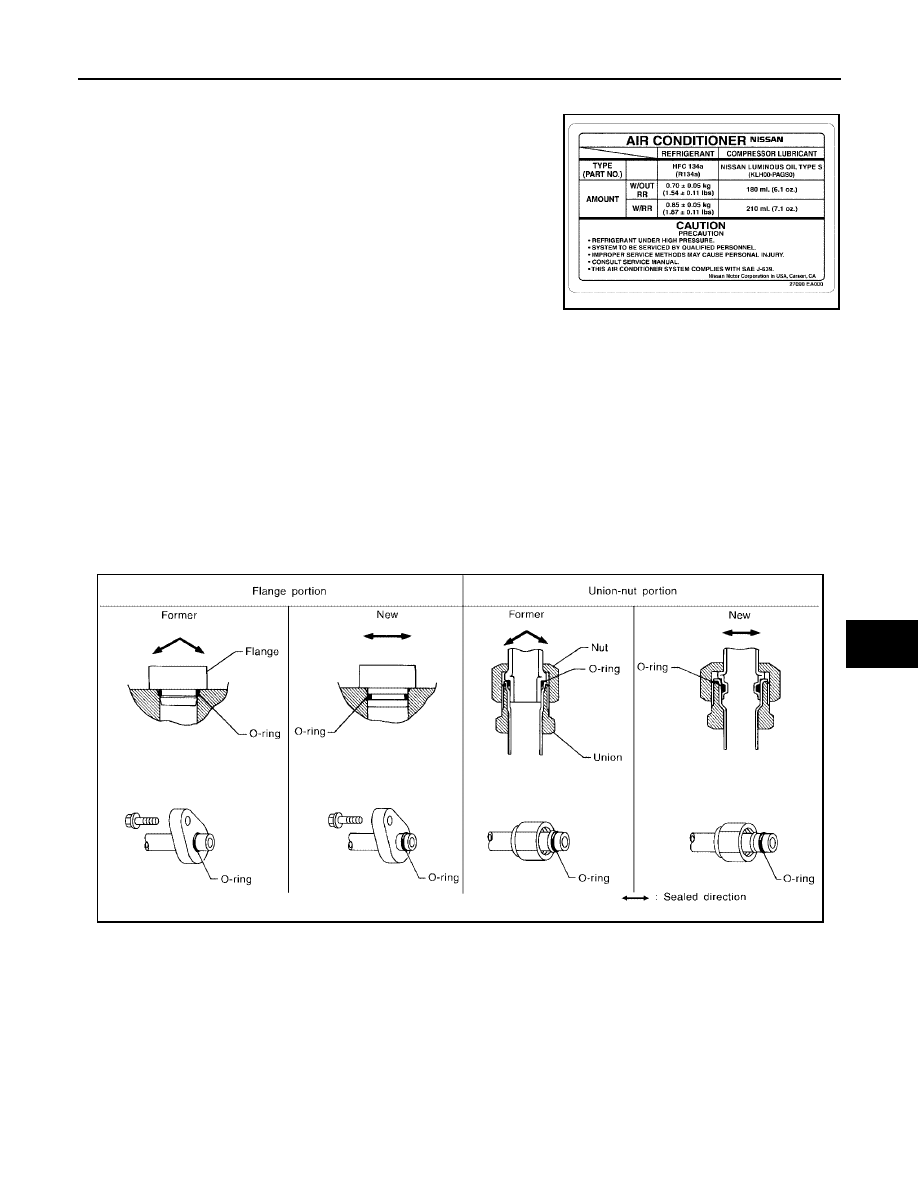
Precautions for Refrigerant Connection

EJS002WA

A new type refrigerant connection has been introduced to all refrigerant lines except the following locations.

Expansion valve to cooling unit

Evaporator pipes to evaporator (inside cooling unit)

Refrigerant pressure sensor

FEATURES OF NEW TYPE REFRIGERANT CONNECTION

The O-ring has been relocated. It has also been provided with a groove for proper installation. This
reduces the possibility of the O-ring being caught in, or damaged by, the mating part. The sealing direction
of the O-ring is now set vertically in relation to the contacting surface of the mating part to improve sealing
characteristics.

The reaction force of the O-ring will not occur in the direction that causes the joint to pull out, thereby facil-
itating piping connections.

LJIA0152E

SHA815E

ATC-8

PRECAUTIONS

2005 Pathfinder

O-RING AND REFRIGERANT CONNECTION

Front A/C Compressor and Condenser

WJIA1399E

PRECAUTIONS

ATC-9

C

D

E

F

G

H

I

K

L

M

A

B

ATC

2005 Pathfinder

Rear A/C

CAUTION:

The new and former refrigerant connections use different O-ring configurations. Do not confuse O-
rings since they are not interchangeable. If a wrong O-ring is installed, refrigerant will leak at or
around the connection.

1.

High-pressure service valve

2.

Clip

3.

Front high-pressure A/C pipe

4.

Refrigerant pressure sensor

5.

Condenser

6.

Compressor shaft seal

7.

Front high-pressure flexible A/C hose

8.

Front low-pressure flexible A/C hose

9.

Low-pressure service valve

10. Front low-pressure A/C pipe

11.

Front expansion valve

12. Front A/C drain hose

WJIA1400E

1.

Rear high- and low-pressure A/C pipes

2.

Rear heater core hoses

3.

Underfloor rear high- and low-pres-
sure A/C and heater core pipes

4.

Rear expansion valve

ATC-10

PRECAUTIONS

2005 Pathfinder

O-Ring Part Numbers and Specifications

*: Always check with the Parts Department for the latest parts information.

WARNING:

Make sure all refrigerant is discharged into the recycling equipment and the pressure in the system is
less than atmospheric pressure. Then gradually loosen the discharge side hose fitting and remove it.

CAUTION:

When replacing or cleaning refrigerant cycle components, observe the following.

When the compressor is removed, store it in the same position as it is when mounted on the car.
Failure to do so will cause lubricant to enter the low pressure chamber.

When connecting tubes, always use a torque wrench and a back-up wrench.

After disconnecting tubes, immediately plug all openings to prevent entry of dirt and moisture.

When installing an air conditioner in the vehicle, connect the pipes as the final stage of the opera-
tion. Do not remove the seal caps of pipes and other components until just before required for
connection.

Allow components stored in cool areas to warm to working area temperature before removing seal
caps. This prevents condensation from forming inside A/C components.

Thoroughly remove moisture from the refrigeration system before charging the refrigerant.

Always replace used O-rings.

When connecting tube, apply lubricant to circle of the O-rings shown in illustration. Be careful not
to apply lubricant to threaded portion.
Lubricant name: Genuine NISSAN A/C System Lubricant Type S (DH-PS) or equivalent.
Part number: KLH00-PAGS0.

O-ring must be closely attached to dented portion of tube.

When replacing the O-ring, be careful not to damage O-ring and tube.

Connect tube until you hear it click, then tighten the nut or bolt by hand until snug. Make sure that
the O-ring is installed to tube correctly.

Connec-
tion type

O-ring

size

Part number*

D

mm (in)

W

mm (in)

New

8

92471 N8210

6.8 (0.268)

1.85 (0.0728)

Former

10

J2476 89956

9.25 (0.3642)

1.78 (0.0701)

New

12

92472 N8210

10.9 (0.429)

2.43 (0.0957)

Former

92475 71L00

11.0 (0.433)

2.4 (0.094)

New

16

92473 N8210

13.6 (0.535)

2.43 (0.0957)

Former

92475 72L00

14.3 (0.563)

2.3 (0.091)

New

19

92474 N8210

16.5 (0.650)

2.43 (0.0957)

Former

92477 N8200

17.12 (0.6740)

1.78 (0.0701)

New

24

92195 AH300

21.8 (0.858)

2.4 (0.094)

SHA814E

PRECAUTIONS

ATC-11

C

D

E

F

G

H

I

K

L

M

A

B

ATC

2005 Pathfinder

After connecting line, conduct leak test and make sure that there is no leakage from connections.
When the refrigerant leaking point is found, disconnect that line and replace the O-ring. Then
tighten connections of seal seat to the specified torque.

Precautions for Servicing Compressor

EJS002WB

Plug all openings to prevent moisture and foreign matter from entering.

When the compressor is removed, store it in the same position as it is when mounted on the car.

When replacing or repairing compressor, follow “Maintenance of Lubricant Quantity in Compres-
sor” exactly. Refer to

ATC-22, "Maintenance of Lubricant Quantity in Compressor"

.

Keep friction surfaces between clutch and pulley clean. If the surface is contaminated with lubri-
cant, wipe it off by using a clean waste cloth moistened with thinner.

After compressor service operation, turn the compressor shaft by hand more than 5 turns in both
directions. This will equally distribute lubricant inside the compressor. After the compressor is
installed, let the engine idle and operate the compressor for 1 hour.

After replacing the compressor magnet clutch, apply voltage to the new one and check for normal
operation. Refer to

ATC-156, "Removal and Installation for Compressor Clutch"

.

Precautions for Service Equipment

EJS002WC

RECOVERY/RECYCLING EQUIPMENT

Follow the manufacturer's instructions for machine operation and machine maintenance. Never introduce any
refrigerant other than that specified into the machine.

ELECTRONIC LEAK DETECTOR

Follow the manufacturer's instructions for tester operation and tester maintenance.

RHA861F

ATC-12

PRECAUTIONS

2005 Pathfinder

VACUUM PUMP

The lubricant contained inside the vacuum pump is not compatible
with the specified lubricant for HFC-134a (R-134a) A/C systems.
The vent side of the vacuum pump is exposed to atmospheric pres-
sure so the vacuum pump lubricant may migrate out of the pump into
the service hose. This is possible when the pump is switched off
after evacuation (vacuuming) and hose is connected to it.
To prevent this migration, use a manual valve situated near the
hose-to-pump connection, as follows.

Usually vacuum pumps have a manual isolator valve as part of
the pump. Close this valve to isolate the service hose from the
pump.

For pumps without an isolator, use a hose equipped with a man-
ual shut-off valve near the pump end. Close the valve to isolate
the hose from the pump.

If the hose has an automatic shut off valve, disconnect the hose
from the pump: as long as the hose is connected, the valve is
open and lubricating oil may migrate.

Some one-way valves open when vacuum is applied and close
under a no vacuum condition. Such valves may restrict the pump's
ability to pull a deep vacuum and are not recommended.

MANIFOLD GAUGE SET

Be certain that the gauge face indicates HFC-134a (R-134a). Make
sure the gauge set has 1/2

-16 ACME threaded connections for ser-

vice hoses. Confirm the set has been used only with refrigerant
HFC-134a (R-134a) along with specified lubricant.

SERVICE HOSES

Be certain that the service hoses display the markings described
(colored hose with black stripe). All hoses must include positive shut-
off devices (either manual or automatic) near the end of the hoses
opposite the manifold gauge.

RHA270D

SHA533D

RHA272D

PRECAUTIONS

ATC-13

C

D

E

F

G

H

I

K

L

M

A

B

ATC

2005 Pathfinder

SERVICE COUPLERS

Never attempt to connect HFC-134a (R-134a) service couplers to a
CFC-12 (R-12) A/C system. The HFC-134a (R-134a) couplers will
not properly connect to the CFC-12 (R-12) system. If an improper
connection is attempted, discharging and contamination may occur.

REFRIGERANT WEIGHT SCALE

Verify that no refrigerant other than HFC134a (R-134a) and specified
lubricants have been used with the scale. If the scale controls refrig-
erant flow electronically, the hose fitting must be 1/2”-16 ACME.

CHARGING CYLINDER

Using a charging cylinder is not recommended. Refrigerant may be vented into air from cylinder's top valve
when filling the cylinder with refrigerant. Also, the accuracy of the cylinder is generally less than that of an
electronic scale or of quality recycle/recharge equipment.

Wiring Diagrams and Trouble Diagnosis

EJS002WD

When you read wiring diagrams, refer to the following:

GI-15, "How to Read Wiring Diagrams"

PG-4, "POWER SUPPLY ROUTING CIRCUIT"

When you perform trouble diagnosis, refer to the following:

GI-9, "How to Follow Trouble Diagnoses"

GI-27, "How to Perform Efficient Diagnosis for an Electrical Incident"

Shut-off valve rotation

A/C service valve

Clockwise

Open

Counterclockwise

Close

RHA273D

RHA274D

ATC-14

PREPARATION

2005 Pathfinder

PREPARATION

PFP:00002

Special Service Tools

EJS002WE

The actual shapes of Kent-Moore tools may differ from those of special service tools illustrated here.

HFC-134a (R-134a) Service Tools and Equipment

EJS003BB

Never mix HFC-134a (R-134a) refrigerant and/or its specified lubricant with CFC-12 (R-12) refrigerant and/or
its lubricant.
Separate and non-interchangeable service equipment must be used for handling each type of refrigerant/lubri-
cant.
Refrigerant container fittings, service hose fittings and service equipment fittings (equipment which handles
refrigerant and/or lubricant) are different between CFC-12 (R-12) and HFC-134a (R-134a). This is to avoid
mixed use of the refrigerants/lubricant.
Adapters that convert one size fitting to another must never be used refrigerant/lubricant contamination will
occur and compressor failure will result.

Tool number
(Kent-Moore No.)
Tool name

Description

(J-38873-A)
Pulley installer

Installing pulley

KV99233130
(J-29884)
Pulley puller

Removing pulley

LHA171

LHA172

Tool number
(Kent-Moore No.)
Tool name

Description

HFC-134a (R-134a)
(

)

Refrigerant

Container color: Light blue
Container marking: HFC-134a (R-
134a)
Fitting size: Thread size

large container 1/2”-16 ACME

KLH00-PAGS0
(

)

NISSAN A/C System Lubricant
Type S (DH-PS)

Type: Poly alkylene glycol oil (PAG),
type S (DH-PS)
Application: HFC-134a (R-134a)
swash plate compressors (NISSAN
only)
Lubricity: 40 m

(1.4 US fl oz, 1.4 Imp

fl oz)

(J-43600)
Recovery/Recycling
Recharging equipment (ACR2000)

Refrigerant Recovery and Recycling
and Recharging

S-NT196

S-NT197

WJIA0293E


Content      ..     43      44      45      46     ..