содержание .. 1466 1467 1468 1469 ..
Nissan Murano Z51. Manual - part 1468
AIR MIX DOOR MOTOR
VTL-43
< REMOVAL AND INSTALLATION >
[WITHOUT 7 INCH DISPLAY]
C
D
E
F
G
H
J
K
L
M
A
B
VTL
N
O
P
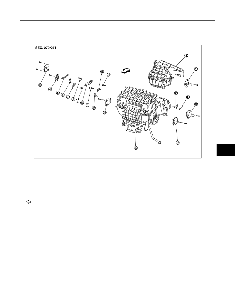
AIR MIX DOOR MOTOR
Exploded View
INFOID:0000000005517133
Removal and Installation
INFOID:0000000005517134
REMOVAL
Driver side
1.
Set the temperature (driver side) at 18
°
C (60
°
F).
CAUTION:
The angle may be out, when installing the air mix door motor to the air mix door, unless the above
procedure is performed.
2.
Disconnect the battery cable from the negative terminal.
3.
Remove the foot duct (left). Refer to
VTL-67, "FOOT DUCT : Exploded View"
.
1.
Intake door motor
2.
Bower unit assembly
3.
Mode door motor
4.
Main link
5.
Rod link
6.
Max. cool door link
7.
Max. cool door link
8.
Mode door lever
9.
Ventilator door link
10. Defroster door link
11.
Ventilator door lever
12. Foot door lever
13. Max. cool door lever
14.
Defroster door lever
15. Air mix door motor (driver side)
16. Heater & cooling unit assembly
17.
Air mix door motor (passenger side) 18. Upper ventilator door motor
19. Upper ventilator door rod
20.
Upper ventilator door lever
: Vehicle front
JPIIA1238ZZ