содержание .. 1464 1465 1466 1467 ..
Nissan Murano Z51. Manual - part 1466
INTAKE DOOR MOTOR
VTL-35
< REMOVAL AND INSTALLATION >
[WITHOUT 7 INCH DISPLAY]
C
D
E
F
G
H
J
K
L
M
A
B
VTL
N
O
P
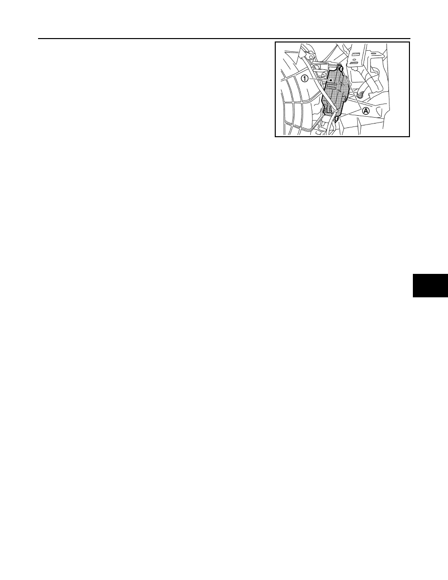
3.
Remove the mounting screws (A), and then remove the intake
door motor (1).
4.
Disconnect the intake door motor connector.
INSTALLATION
Install in the reverse order of removal.
JPIIA0570ZZ