содержание .. 1463 1464 1465 1466 ..
Nissan Murano Z51. Manual - part 1465
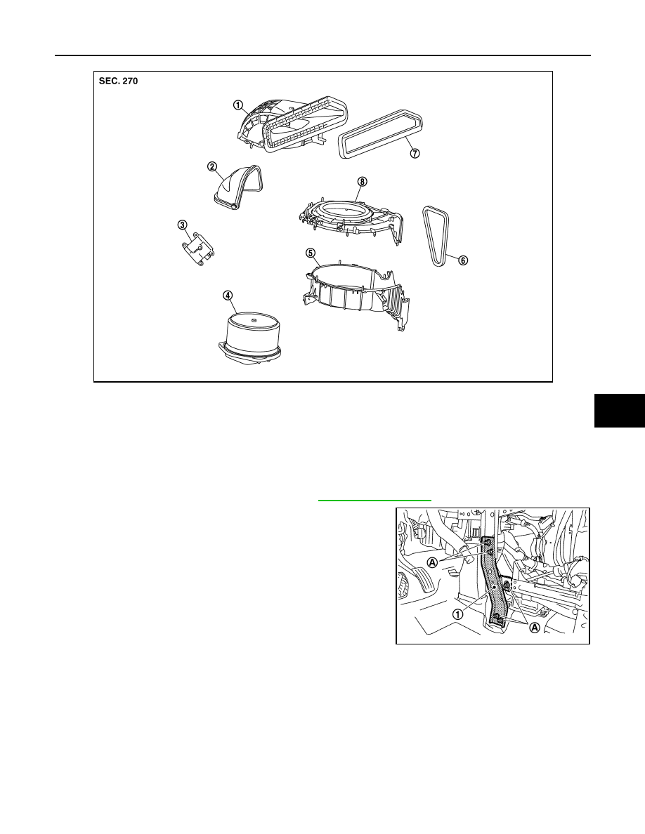
BLOWER UNIT
VTL-31
< REMOVAL AND INSTALLATION >
[WITHOUT 7 INCH DISPLAY]
C
D
E
F
G
H
J
K
L
M
A
B
VTL
N
O
P
Removal and Installation
INFOID:0000000005517122
REMOVAL
1.
Remove the instrument panel assembly. Refer to
.
2.
Remove the mounting nuts (A), and then remove the instrument
panel stay (1).
3.
Disconnect the intake door motor and blower motor connectors.
1.
Shutter box case
2.
Intake door
3.
Intake door motor
4.
Blower motor assembly
5.
Intake lower case
6.
Outlet seal
7.
Intake seal
8.
Intake upper case
JPIIA0455ZZ
JPIIA0565ZZ