содержание .. 1465 1466 1467 1468 ..
Nissan Murano Z51. Manual - part 1467
HEATER & COOLING UNIT ASSEMBLY
VTL-39
< REMOVAL AND INSTALLATION >
[WITHOUT 7 INCH DISPLAY]
C
D
E
F
G
H
J
K
L
M
A
B
VTL
N
O
P
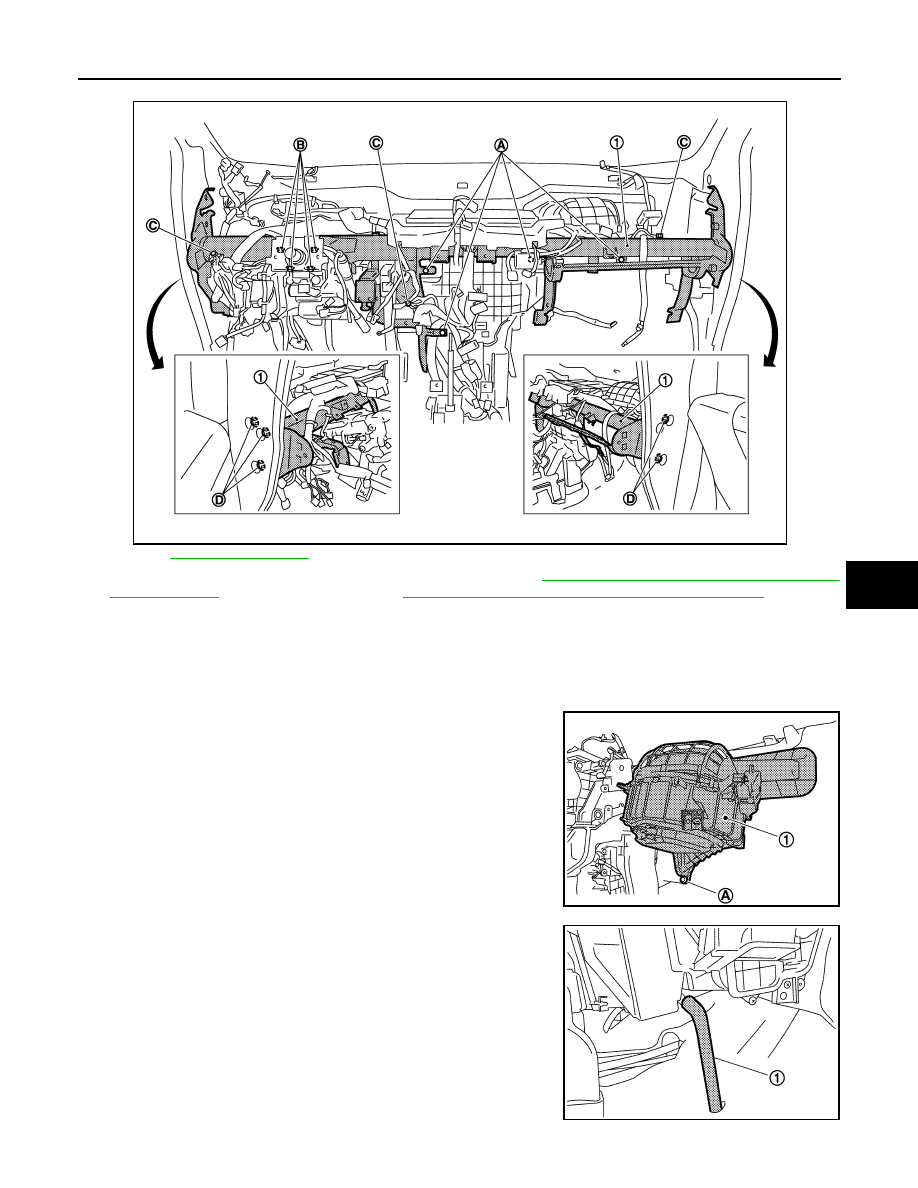
7.
Remove the heater & cooling unit assembly and blower unit mounting bolts (A).
for symbols shown in the figure.
8.
Remove the steering column mounting nuts (B). Refer to
ST-18, "WITHOUT ELECTRIC MOTOR :
ST-21, "WITH ELECTRIC MOTOR : Exploded View"
(with elec-
tric motor).
9.
Remove the ground bolts (C) from the steering member (1).
10. Remove the harness clip from the steering member.
11. Disconnect the intake door motor and blower motor connectors.
12. Remove the steering member mounting bolts (D), and then remove the steering member.
13. Remove the mounting screw (A), and then remove the blower
unit (1).
14. Disconnect the drain hose (1) from heater & cooling unit assem-
bly.
JPIIA1241ZZ
JPIIA0567ZZ
JPIIA0572ZZ