Murano Cross Cabriolet Z51 (2013 year). Manual - part 53


  Index      Manuals     Murano Cross Cabriolet Z51 (2013 year) - Service and Repair Manual


Search            copyright infringement  


Content      ..     51      52      53      54     ..


Murano Cross Cabriolet Z51 (2013 year). Manual - part 53


INL-36

< REMOVAL AND INSTALLATION >

MAP LAMP

2.

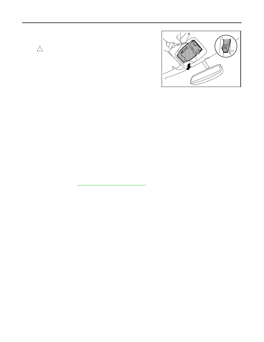
Remove map lamp assembly.

a.

Disengage map lamp assembly fixing pawls using a remover
tool (A).

b.

Disconnect harness connector, and then remove map lamp assembly.

INSTALLATION

Install in the reverse order of removal.

Replacement

INFOID:0000000008460387

CAUTION:

• Disconnect the battery negative terminal or remove power circuit fuse while performing the opera-

tion to prevent electric leakage.

• Never touch the glass surface of the bulb with bare hands or allow oil or grease to get on it to pre-

vent damage to the bulb.

• Never touch the glass surface of the bulb with bare hands because the surface is very hot just after

the lamp is turned OFF to prevent a burns.

• Leaving the bulb removed from housing for a long period of time can deteriorate performance of the

lens and reflector (causing dirty or clouding). Always prepare a new bulb and have it on hand when
replacing the bulb.

MAP LAMP BULB

1.

Remove lens. Refer to 

INL-35, "Removal and Installation"

.

2.

Remove bulb.

: Pawl

JMLIA2228ZZ

Revision: 2012 October

2013 Murano CrossCabriolet

VANITY MIRROR LAMP

INL-37

< REMOVAL AND INSTALLATION >

C

D

E

F

G

H

I

J

K

M

A

B

INL

N

O

P

VANITY MIRROR LAMP

Exploded View

INFOID:0000000008460388

Replacement

INFOID:0000000008460389

CAUTION:

• Disconnect the battery negative terminal or remove power circuit fuse while performing the opera-

tion to prevent electric leakage.

• Never touch the glass surface of the bulb with bare hands or allow oil or grease to get on it to pre-

vent damage to the bulb.

• Never touch the glass surface of the bulb with bare hands because the surface is very hot just after

the lamp is turned OFF to prevent a burns.

• Leaving the bulb removed from housing for a long period of time can deteriorate performance of the

lens and reflector (causing dirty or clouding). Always prepare a new bulb and have it on hand when
replacing the bulb.

• When using a small flat-bladed screwdriver, apply protective tape on tip of a small flat-bladed screw-

driver to protect parts from damage.

VANITY MIRROR LAMP BULB

1.

Disengage lens fixing pawls using a remover tool (A).

CAUTION:

Apply protective tape (B) on the parts to protect it from
damage.

2.

Remove bulb.

1.

Lens

2.

Bulb

3.

Sun visor

: Pawl

JMLIA2229ZZ

: Pawl

JMLIA2230ZZ

Revision: 2012 October

2013 Murano CrossCabriolet

INL-38

< REMOVAL AND INSTALLATION >

GLOVE BOX LAMP

GLOVE BOX LAMP

Exploded View

INFOID:0000000008460390

Replacement

INFOID:0000000008460391

CAUTION:

• Disconnect the battery negative terminal or remove power circuit fuse while performing the opera-

tion to prevent electric leakage.

• Never touch the glass surface of the bulb with bare hands or allow oil or grease to get on it to pre-

vent damage to the bulb.

• Never touch the glass surface of the bulb with bare hands because the surface is very hot just after

the lamp is turned OFF to prevent a burns.

• Leaving the bulb removed from housing for a long period of time can deteriorate performance of the

lens and reflector (causing dirty or clouding). Always prepare a new bulb and have it on hand when
replacing the bulb.

GLOVE BOX LAMP BULB

1.

Remove instrument lower panel RH. Refer to 

IP-13, "Removal and Installation"

.

2.

Rotate the bulb & socket assembly counterclockwise and unlock
it and then remove bulb & socket assembly.

1.

Instrument lower panel RH

2.

Bulb & socket assembly

3.

Lamp housing

: Pawl

: Vehicle front

JMLIA2231ZZ

JMLIA1528ZZ

Revision: 2012 October

2013 Murano CrossCabriolet

CONSOLE POCKET LAMP

INL-39

< REMOVAL AND INSTALLATION >

C

D

E

F

G

H

I

J

K

M

A

B

INL

N

O

P

CONSOLE POCKET LAMP

Exploded View

INFOID:0000000008460392

Replacement

INFOID:0000000008460393

CAUTION:

• Disconnect the battery negative terminal or remove power circuit fuse while performing the opera-

tion to prevent electric leakage.

• Never touch the glass surface of the bulb with bare hands or allow oil or grease to get on it to pre-

vent damage to the bulb.

• Never touch the glass surface of the bulb with bare hands because the surface is very hot just after

the lamp is turned OFF to prevent a burns.

• Leaving the bulb removed from housing for a long period of time can deteriorate performance of the

lens and reflector (causing dirty or clouding). Always prepare a new bulb and have it on hand when
replacing the bulb.

CONSOLE POCKET LAMP BULB

1.

Remove cluster lid C (lower). Refer to 

IP-13, "Removal and Installation"

.

2.

Rotate the bulb & socket assembly counterclockwise and unlock
it and then remove bulb & socket assembly.

1.

Cluster lid C (lower)

2.

Lamp housing

3.

Bulb & socket assembly

: Pawl

: Vehicle front

JMLIA2232ZZ

JMLIA1528ZZ

Revision: 2012 October

2013 Murano CrossCabriolet

INL-40

< REMOVAL AND INSTALLATION >

STEP LAMP

STEP LAMP

Exploded View

INFOID:0000000008460394

Removal and Installation

INFOID:0000000008460395

CAUTION:

• Disconnect the battery negative terminal or remove power circuit fuse while performing the opera-

tion to prevent electric leakage.

• When removing, always use a remover tool that is made of plastic to prevent damage to the parts.

REMOVAL

1.

Disengage step lamp fixing metal clips using a remover tool (A).

CAUTION:

Apply protective tape (B) on the parts to protect it from
damage.

2.

Disconnect harness connector, and then remove step lamp.

INSTALLATION

Install in the reverse order of removal.

Replacement

INFOID:0000000008460396

CAUTION:

• Disconnect the battery negative terminal or remove power circuit fuse while performing the opera-

tion to prevent electric leakage.

1.

Front door finisher

2.

Lamp housing

3.

Bulb

4.

Lens

: Pawl

: Metal clip

: Vehicle front

JMLIA2233ZZ

: Metal clip

JMLIA2234ZZ

Revision: 2012 October

2013 Murano CrossCabriolet

STEP LAMP

INL-41

< REMOVAL AND INSTALLATION >

C

D

E

F

G

H

I

J

K

M

A

B

INL

N

O

P

• Never touch the glass surface of the bulb with bare hands or allow oil or grease to get on it to pre-

vent damage to the bulb.

• Never touch the glass surface of the bulb with bare hands because the surface is very hot just after

the lamp is turned OFF to prevent a burns.

• Leaving the bulb removed from housing for a long period of time can deteriorate performance of the

lens and reflector (causing dirty or clouding). Always prepare a new bulb and have it on hand when
replacing the bulb.

STEP LAMP BULB

1.

Remove step lamp. Refer to 

INL-40, "Removal and Installation"

.

2.

Remove lens.
Disengage lens fixing pawls using a remover tool (A), and then
remove lens.

3.

Remove bulb.

: Pawl

JMLIA2235ZZ

Revision: 2012 October

2013 Murano CrossCabriolet

INL-42

< REMOVAL AND INSTALLATION >

TRUNK ROOM LAMP

TRUNK ROOM LAMP

Exploded View

INFOID:0000000008460397

Removal and Installation

INFOID:0000000008460398

CAUTION:

• Disconnect the battery negative terminal or remove power circuit fuse while performing the opera-

tion to prevent electric leakage.

• When removing, always use a remover tool that is made of plastic to prevent damage to the parts.

REMOVAL

1.

Disengage trunk room lamp fixing metal clips using a remover
tool (A).

CAUTION:

Apply protective tape (B) on the parts to protect it from
damage.

2.

Disconnect harness connector, and then remove trunk room lamp.

INSTALLATION

Install in the reverse order of removal.

Replacement

INFOID:0000000008460399

CAUTION:

• Disconnect the battery negative terminal or remove power circuit fuse while performing the opera-

tion to prevent electric leakage.

1.

Lamp housing

2.

Bulb

3.

Lens

: Pawl

: Metal clip

: Vehicle front

JMLIA2236ZZ

: Metal clip

JMLIA2237ZZ

Revision: 2012 October

2013 Murano CrossCabriolet

TRUNK ROOM LAMP

INL-43

< REMOVAL AND INSTALLATION >

C

D

E

F

G

H

I

J

K

M

A

B

INL

N

O

P

• Never touch the glass surface of the bulb with bare hands or allow oil or grease to get on it to pre-

vent damage to the bulb.

• Never touch the glass surface of the bulb with bare hands because the surface is very hot just after

the lamp is turned OFF to prevent a burns.

• Leaving the bulb removed from housing for a long period of time can deteriorate performance of the

lens and reflector (causing dirty or clouding). Always prepare a new bulb and have it on hand when
replacing the bulb.

TRUNK ROOM LAMP BULB

1.

Remove trunk room lamp. Refer to 

INL-42, "Removal and Installation"

.

2.

Remove lens.
Disengage lens fixing pawls using a remover tool (A), and then
remove lens.

3.

Remove bulb.

: Pawl

JMLIA2235ZZ

Revision: 2012 October

2013 Murano CrossCabriolet

INL-44

< SERVICE DATA AND SPECIFICATIONS (SDS) 

SERVICE DATA AND SPECIFICATIONS (SDS)

SERVICE DATA AND SPECIFICATIONS (SDS)

SERVICE DATA AND SPECIFICATIONS (SDS)

Bulb Specifications

INFOID:0000000008460400

Item

Type

Wattage (W)

Push-button ignition switch illumination

LED

Map lamp

Wedge

8

Vanity mirror lamp

2

Console pocket lamp

Wedge

1.4

Glove box lamp

Wedge

2.0

Step lamp

Wedge

2.7

Trunk room lamp

Wedge

5

Revision: 2012 October

2013 Murano CrossCabriolet

IP-1

BODY INTERIOR

C

D

E

F

G

H

I

K

L

M

SECTION 

IP

A

B

IP

N

O

P

CONTENTS

INSTRUMENT PANEL

SYMPTOM DIAGNOSIS  ...............................

2

SQUEAK AND RATTLE TROUBLE DIAG-
NOSES ................................................................

2

Work Flow  .................................................................

2

Inspection Procedure  ................................................

4

Diagnostic Worksheet  ...............................................

6

PRECAUTION ...............................................

8

PRECAUTIONS ...................................................

8

Precaution for Supplemental Restraint System 
(SRS) "AIR BAG" and "SEAT BELT PRE-TEN-
SIONER" .................................................................
..

8

Service Procedure Precautions for Models with a 
Pop-up Roll Bar .......................................................
..

8

Precaution .................................................................

8

PREPARATION ...........................................

10

PREPARATION .................................................

10

Special Service Tools ............................................

10

Commercial Service Tools .....................................

10

CLIP LIST ..........................................................

11

Clip List ....................................................................

11

REMOVAL AND INSTALLATION  ...............

12

INSTRUMENT PANEL ASSEMBLY  .................

12

Exploded View .........................................................

12

Removal and Installation  .........................................

13

CENTER CONSOLE ASSEMBLY  ....................

20

Exploded View .........................................................

20

Removal and Installation  .........................................

21

Revision: 2012 October

2013 Murano CrossCabriolet

IP-2

< SYMPTOM DIAGNOSIS >

SQUEAK AND RATTLE TROUBLE DIAGNOSES

SYMPTOM DIAGNOSIS

SQUEAK AND RATTLE TROUBLE DIAGNOSES

Work Flow

INFOID:0000000008462955

CUSTOMER INTERVIEW

Interview the customer if possible, to determine the conditions that exist when the noise occurs. Use the Diag-
nostic Worksheet during the interview to document the facts and conditions when the noise occurs and any
customer comments. Refer to 

IP-6, "Diagnostic Worksheet"

. This information is necessary to duplicate the

conditions that exist when the noise occurs.
• The customer may not be able to provide a detailed description or the location of the noise. Attempt to obtain

all the facts and conditions that exist when the noise occurs (or does not occur).

• If there is more than one noise in the vehicle, perform a diagnosis and repair the noise that the customer is

concerned about. This can be accomplished by performing a test drive with the customer.

• After identifying the type of noise, isolate the noise in terms of its characteristics. The noise characteristics

are provided so that the customer, service adviser, and technician use the same language when describing
the noise.

• Squeak – (Like tennis shoes on a clean floor)

Squeak characteristics include the light contact / fast movement / brought on by road conditions / hard sur-
faces = high-pitched noise / softer surfaces = low-pitched noises / edge to surface = chirping

• Creak – (Like walking on an old wooden floor)

Creak characteristics include firm contact / slow movement/twisting with a rotational movement / pitch
dependent on materials / often brought on by activity.

• Rattle – (Like shaking a baby rattle)

Rattle characteristics include fast repeated contact / vibration or similar movement / loose parts/missing clip
or fastener / incorrect clearance.

• Knock – (Like a knock on a door)

Knock characteristics include hollow sounds / sometimes repeating / often brought on by driver action.

• Tick – (Like a clock second hand)

Tick characteristics include gentle contacting of light materials / loose components / can be caused by driver
action or road conditions.

• Thump – (Heavy, muffled knock noise)

Thump characteristics include softer knock / dull sounds often brought on by activity.

• Buzz – (Like a bumblebee)

Buzz characteristics include high frequency rattle / firm contact.

• Often the degree of acceptable noise level varies depending upon the person. A noise that a technician may

judge as acceptable may be very irritating to a customer.

• Weather conditions, especially humidity and temperature, may have a great effect on noise level.

DUPLICATE THE NOISE AND TEST DRIVE

SBT842

Revision: 2012 October

2013 Murano CrossCabriolet

SQUEAK AND RATTLE TROUBLE DIAGNOSES

IP-3

< SYMPTOM DIAGNOSIS >

C

D

E

F

G

H

I

K

L

M

A

B

IP

N

O

P

If possible, drive the vehicle with the customer until the noise is duplicated. Note any additional information on
the Diagnostic Worksheet regarding the conditions or location of the noise. This information can be used to
duplicate the same conditions when the repair is reconfirmed.
If the noise can be duplicated easily during the test drive, to help identify the source of the noise, try to dupli-
cate the noise with the vehicle stopped by doing one or all of the following items:
1) Close a door.
2) Tap or push/pull around the area where the noise appears to be coming from.
3) Rev the engine.
4) Use a floor jack to recreate vehicle “twist”.
5) At idle, apply engine load (electrical load, half-clutch on M/T models, drive position on A/T models).
6) Raise the vehicle on a hoist and hit a tire with a rubber hammer.
• Drive the vehicle and attempt to duplicate the conditions the customer states exist when the noise occurs.
• If it is difficult to duplicate the noise, drive the vehicle slowly on an undulating or rough road to stress the

vehicle body.

CHECK RELATED SERVICE BULLETINS

After verifying the customer concern or symptom, check ASIST for Technical Service Bulletins (TSBs) related
to the concern or symptom.
If a TSB relates to the symptom, follow the procedure to repair the noise.

LOCATE THE NOISE AND IDENTIFY THE ROOT CAUSE

1.

Narrow down the noise to a general area. To help pinpoint the source of the noise, use a listening tool
(Chassis ear: J-39570, engine ear, and mechanics stethoscope).

2.

Narrow down the noise to a more specific area and identify the cause of the noise by:

• Removing the component(s) in the area that is / are suspected to be the cause of the noise.

Do not use too much force when removing clips and fasteners, otherwise clips and fasteners can be broken
or lost during the repair, resulting in the creation of new noise.

• Tapping or pushing/pulling the component(s) that is / are suspected to be the cause of the noise.

Do not tap or push/pull the component(s) with excessive force, otherwise the noise is eliminated only tempo-
rarily.

• Feeling for a vibration by hand by touching the component(s) that is / are suspected to be the cause of the

noise.

• Placing a piece of paper between components that are suspected to be the cause of the noise.
• Looking for loose components and contact marks.

Refer to 

IP-4, "Inspection Procedure"

.

REPAIR THE CAUSE

• If the cause is a loose component, tighten the component securely.
• If the cause is insufficient clearance between components:
- Separate components by repositioning or loosening and retightening the components, if possible.
- Insulate components with a suitable insulator such as urethane pads, foam blocks, felt cloth tape, or ure-

thane tape. A NISSAN Squeak and Rattle Kit (J-43980) is available through the authorized NISSAN Parts
Department.

CAUTION:

Never use excessive force as many components are constructed of plastic and may be damaged.
NOTE:
Always check with the Parts Department for the latest parts information.
The following materials are contained in the NISSAN Squeak and Rattle Kit (J-43980). Each item can be
ordered separately as needed.
URETHANE PADS [1.5 mm (0.059 in) thick]
Insulates connectors, harness, etc.
• 76268-9E005: 100

×

135 mm (3.937

×

5.315 in)

• 76884-71L01: 60

×

85 mm (2.362

×

3.346 in)

• 76884-71L02: 15

×

25 mm (0.591

×

0.984 in)

INSULATOR (Foam blocks)
Insulates components from contact. Can be used to fill space behind a panel.
• 73982-9E000: 45 mm (1.772 in) thick, 50

×

50 mm (1.969

×

1.969 in)

• 73982-50Y00: 10 mm (0.394 in) thick, 50

×

50 mm (1.969

×

1.969 in)

INSULATOR (Light foam block)
80845-71L00: 30 mm (1.18 in) thick, 30

×

50 mm (1.181

×

1.969in)

FELT CLOTHTAPE

Revision: 2012 October

2013 Murano CrossCabriolet

IP-4

< SYMPTOM DIAGNOSIS >

SQUEAK AND RATTLE TROUBLE DIAGNOSES

Used to insulate where movement does not occur. Ideal for instrument panel applications.
• 68370-4B000: 15

×

25 mm (0.591

×

0.984 in) pad

• 68239-13E00: 5 mm (0.197 in) wide tape roll
The following materials, not found in the kit, can also be used to repair squeaks and rattles.
UHMW (TEFLON) TAPE
Insulates where slight movement is present. Ideal for instrument panel applications.
SILICONE GREASE
Used in place of UHMW tape that is visible or does not fit. Only lasts a few months.
SILICONE SPRAY
Used when grease cannot be applied.
DUCT TAPE
Used to eliminate movement.

CONFIRM THE REPAIR

After repair is complete, test drive the vehicle to confirm that the cause of noise is repaired by test driving the
vehicle. Operate the vehicle under the same conditions as when the noise originally occurred. Refer to the
notes on the Diagnostic Worksheet.

Inspection Procedure

INFOID:0000000008462956

Refer to Table of Contents for specific component removal and installation information.

INSTRUMENT PANEL

Most incidents are caused by contact and movement between:

1.

The cluster lid A and instrument panel

2.

Acrylic lens and combination meter housing

3.

Instrument panel to front pillar garnish

4.

Instrument panel to windshield

5.

Instrument panel mounting pins

6.

Wiring harnesses behind the combination meter

7.

A/C defroster duct and duct joint
These incidents can usually be located by tapping or moving the components to duplicate the noise or by
pressing on the components while driving to stop the noise. Most of these incidents can be repaired by
applying felt cloth tape or silicon spray (in hard to reach areas). Urethane pads can be used to insulate
wiring harness.

CAUTION:

Never use silicone spray to isolate a squeak or rattle. If the area is saturated with silicone, the
recheck of repair becomes impossible.

CENTER CONSOLE

Components to check include:

1.

Shifter assembly cover to finisher

2.

A/C control unit and cluster lid C

3.

Wiring harnesses behind audio and A/C control unit

The instrument panel repair and isolation procedures also apply to the center console.

DOORS

Check the following items:

1.

Finisher and inner panel making a slapping noise

2.

Inside handle escutcheon connection to door finisher

3.

Wiring harnesses tapping

4.

Door striker out of alignment causing a popping noise on starts and stops

Tapping, moving the components, or pressing on them while driving to duplicate the conditions can isolate
many of these incidents. The areas can usually be insulated with felt cloth tape or insulator foam blocks from
the NISSAN Squeak and Rattle Kit (J-43980) to repair the noise.

TRUNK

Trunk noises are often caused by a loose jack or loose items put into the trunk by the customer.
In addition check for the following items:

Revision: 2012 October

2013 Murano CrossCabriolet

SQUEAK AND RATTLE TROUBLE DIAGNOSES

IP-5

< SYMPTOM DIAGNOSIS >

C

D

E

F

G

H

I

K

L

M

A

B

IP

N

O

P

1.

Trunk lid dumpers out of adjustment

2.

Trunk lid striker out of adjustment

3.

Trunk lid torsion bars knocking together

4.

A loose license plate or bracket

Most of these incidents can be repaired by adjusting, securing, or insulating the item(s) or component(s) caus-
ing the noise.

SUNROOF/HEADLINING

Noises in the sunroof / headlining area can often be traced to one of the following items:

1.

Sunroof lid, rail, linkage, or seals making a rattle or light knocking noise

2.

Sunvisor shaft shaking in the holder

3.

Front or rear windshield touching headlining and squeaking

Again, pressing on the components to stop the noise while duplicating the conditions can isolate most of these
incidents. Repairs usually consist of insulating with felt cloth tape.

SEATS

When isolating seat noise it is important to note the position the seat is in and the load placed on the seat
when the noise occurs. These conditions should be duplicated when verifying and isolating the cause of the
noise.
Causes of seat noise include:
1.

Headrest rods and holder

2.

A squeak between the seat pad cushion and frame

3.

The rear seatback lock and bracket

These noises can be isolated by moving or pressing on the suspected components while duplicating the con-
ditions under which the noise occurs. Most of these incidents can be repaired by repositioning the component
or applying urethane tape to the contact area.

UNDERHOOD

Some interior noise may be caused by components under the hood or on the engine wall. The noise is then
transmitted into the passenger compartment.
Causes of transmitted underhood noise include:

1.

Any component mounted to the engine wall

2.

Components that pass through the engine wall

3.

Engine wall mounts and connectors

4.

Loose radiator mounting pins

5.

Hood bumpers out of adjustment

6.

Hood striker out of adjustment

These noises can be difficult to isolate since they cannot be reached from the interior of the vehicle. The best
method is to secure, move, or insulate one component at a time and test drive the vehicle. Also, engine RPM
or load can be changed to isolate the noise. Repairs can usually be made by moving, adjusting, securing, or
insulating the component causing the noise.

Revision: 2012 October

2013 Murano CrossCabriolet

IP-6

< SYMPTOM DIAGNOSIS >

SQUEAK AND RATTLE TROUBLE DIAGNOSES

Diagnostic Worksheet

INFOID:0000000008462957

PIIB8740E

Revision: 2012 October

2013 Murano CrossCabriolet

SQUEAK AND RATTLE TROUBLE DIAGNOSES

IP-7

< SYMPTOM DIAGNOSIS >

C

D

E

F

G

H

I

K

L

M

A

B

IP

N

O

P

PIIB8742E

Revision: 2012 October

2013 Murano CrossCabriolet


Content      ..     51      52      53      54     ..