Murano Cross Cabriolet Z51 (2013 year). Manual - part 51


  Index      Manuals     Murano Cross Cabriolet Z51 (2013 year) - Service and Repair Manual


Search            copyright infringement  


Content      ..     49      50      51      52     ..


Murano Cross Cabriolet Z51 (2013 year). Manual - part 51


INL-4

< SYSTEM DESCRIPTION >

COMPONENT PARTS

SYSTEM DESCRIPTION

COMPONENT PARTS

INTERIOR LIGHTING SYSTEM

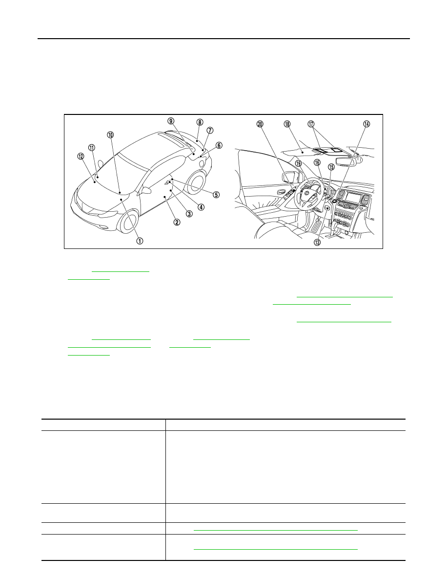
INTERIOR LIGHTING SYSTEM : Component Parts Location

INFOID:0000000008460360

INTERIOR LIGHTING SYSTEM : Component Description

INFOID:0000000008460361

1.

IPDM E/R
Refer to 

PCS-4, "Component 

Parts Location"

2.

Step lamp

3.

Door switch

4.

Door request switch

5.

Door key cylinder switch

6.

Rear remote keyless entry receiver
Refer to 

DLK-10, "DOOR LOCK SYSTEM : 

Component Parts Location"

7.

Trunk room lamp

8.

Trunk room lamp switch

9.

Soft top control unit
Refer to 

RF-9, "Component Parts Location"

10. BCM

Refer to 

BCS-4, "BODY CON-

TROL SYSTEM : Component 
Parts Location"

11. Optical sensor

Refer to 

EXL-6, "Component 

Parts Location"

12.

Front remote keyless entry receiver

13. Key slot

14. Push-button ignition switch

15.

Combination switch

16. Combination meter

17. Map lamp

18.

Vanity mirror lamp

19. Illumination control switch

20. Door lock and unlock switch

JMLIA2206ZZ

Part

Description

BCM

• Activates the interior room lamp timer depending on the vehicle condition to turn the 

interior room lamp ON/OFF.

• Turns the step lamp ON /OFF according to any door switch status.
• Operates the interior room lamp battery saver depending on the vehicle condition to 

cut the interior room lamp power supply. 

• Detects each switch condition by the combination switch reading function.
• Judges the illumination lamp ON/OFF status depending on the vehicle condition. 

And then it transmits position light request signal to IPDM E/R and combination 
meter (with CAN communication). 

IPDM E/R

Controls the integrated relay according to the request from BCM (with CAN communi-
cation).

Remote keyless entry receiver

Refer to 

DLK-11, "DOOR LOCK SYSTEM : Component Description"

.

• Door request switch
• Door key cylinder switch
• Door lock/unlock switch

Refer to 

DLK-11, "DOOR LOCK SYSTEM : Component Description"

.

Revision: 2012 October

2013 Murano CrossCabriolet

COMPONENT PARTS

INL-5

< SYSTEM DESCRIPTION >

C

D

E

F

G

H

I

J

K

M

A

B

INL

N

O

P

• Door switch
• Trunk room lamp switch

Refer to 

DLK-11, "DOOR LOCK SYSTEM : Component Description"

.

Key slot

Refer to 

DLK-11, "DOOR LOCK SYSTEM : Component Description"

.

Optical sensor

Refer to 

EXL-7, "Component Description"

.

Combination meter

Refer to 

MWI-8, "METER SYSTEM : System Description"

.

Combination switch
(Lighting & turn signal switch)

Refer to 

BCS-6, "COMBINATION SWITCH READING SYSTEM : System Description"

.

Part

Description

Revision: 2012 October

2013 Murano CrossCabriolet

INL-6

< SYSTEM DESCRIPTION >

SYSTEM

SYSTEM

INTERIOR ROOM LAMP CONTROL SYSTEM

INTERIOR ROOM LAMP CONTROL SYSTEM : System Diagram

INFOID:0000000008460362

INTERIOR ROOM LAMP CONTROL SYSTEM : System Description

INFOID:0000000008460363

OUTLINE

• Interior room lamps* are controlled by interior room lamp timer control function of BCM. 

*: Map lamp (when map lamp switch is in DOOR position).

• Step lamp is controlled by step lamp control function of BCM.
• Trunk room lamp is controlled by trunk room lamp control function of BCM.
• Push-button ignition switch illumination is controlled by the push-button ignition switch illumination control

function of BCM.

INTERIOR ROOM LAMP TIMER CONTROL

Interior Room Lamp Timer Basic Operation

• The interior room lamp turns ON and OFF (gradual brightening and dimming) by the interior room timer.

JMLIA2222GB

JPLIA0093GB

Revision: 2012 October

2013 Murano CrossCabriolet

SYSTEM

INL-7

< SYSTEM DESCRIPTION >

C

D

E

F

G

H

I

J

K

M

A

B

INL

N

O

P

• BCM judges the vehicle condition with the following items. It activates the interior room timer.
- Ignition switch status
- Door switch signal (ALL)
- Door lock/unlock signal (Remote keyless entry receiver, each door request switch, door key cylinder switch,

door lock and unlock switch)

NOTE:
Each function of interior room lamp timer can be set by CONSULT. Refer to 

INL-12, "INT LAMP : CONSULT

Function (BCM - INT LAMP)"

.

Interior Room Lamp ON Operation

• BCM always turns the interior room lamp ON when any door opens.
• BCM activates the interior room timer in any of the following conditions to turn the interior room lamp ON for

a period of time.

- Any door opens before all doors close.
- Ignition switch is turned ON 

 OFF.

- Any door unlock signal is detected when all doors close with ignition switch OFF. 
NOTE:
Restart the timer if new condition is input during the timer operating time.

Interior Room Lamp OFF Operation

BCM stops the timer in any of the following conditions to turn the interior room lamp OFF.
• The timer operating time is expired.
• Ignition switch position is other than OFF with all doors close.
• Any door lock operation is detected with all doors close.

STEP LAMP CONTROL

BCM controls the step lamp (ground-side) to turn ON with any door switch ON.

TRUNK ROOM LAMP CONTROL

BCM turns trunk room lamp ON when the following condition is detected.
• Trunk room lamp switch is ON
BCM turns trunk room lamp OFF when the following condition is detected.
• Trunk room lamp switch is OFF

PUSH-BUTTON IGNITION SWITCH ILLUMINATION CONTROL

Push-button Ignition Switch Illumination Basic Operation

• BCM provides the power supply and the ground to turn the push-button ignition switch illumination ON.
• BCM cuts the ground supply while the each illumination (tail lamp) ON. BCM switches to the ground control

with the meter illumination control function.

Push-button Ignition Switch Illumination ON Operation

BCM turns the push-button ignition switch illumination ON in the following conditions.
• Ignition switch ON
• Each illumination (tail lamp) ON
• Any of the following conditions with ignition switch OFF
- Engine start permission is entered.
- Intelligent Key inserted into the key slot. 
- Driver door is LOCK 

 UNLOCK.

- Driver door is open.

Push-button Ignition Switch Illumination OFF Operation

BCM turns the push-button ignition switch illumination OFF in any of the following conditions.
• The push-button ignition switch illumination ON conditions do not satisfy.
• All of the following conditions with ignition switch OFF
- Each illumination (tail lamp) OFF
- The push-button ignition switch illumination ON conditions do not change (15 seconds after the ignition

switch OFF) or the driver door is UNLOCK 

 LOCK.

INTERIOR ROOM LAMP BATTERY SAVER SYSTEM

Revision: 2012 October

2013 Murano CrossCabriolet

INL-8

< SYSTEM DESCRIPTION >

SYSTEM

INTERIOR ROOM LAMP BATTERY SAVER SYSTEM : System Diagram

INFOID:0000000008460364

INTERIOR ROOM LAMP BATTERY SAVER SYSTEM : System Description

INFOID:0000000008460365

OUTLINE

• Interior room lamp battery saver is controlled by BCM.
• BCM turns applicable lamps OFF depending on the vehicle condition. This function prevents the battery

from over-discharging if the driver neglect turning OFF the any lamps.

Applicable lamps

• Map lamp
• Step lamp
• Trunk room lamp
• Vanity mirror lamp

INTERIOR ROOM LAMP BATTERY SAVER FUNCTION

• When the ignition switch is turned OFF, BCM operates the timer for a period of time to cut the interior room

lamp power supply.

• BCM restart the timer when any of the following signals changes while operating the timer.
- Ignition switch status
- Door switch signal (ALL)
- Door lock/unlock signal (Remote keyless entry receiver, each door request switch, door key cylinder switch,

door lock and unlock switch)

- Key switch signal (Key slot)
• BCM provides the interior room lamp power supply continuously when the ignition switch position is other

than OFF.

NOTE:
Each function of interior room lamp battery saver can be set by CONSULT. Refer to 

INL-14, "BATTERY

SAVER : CONSULT Function (BCM - BATTERY SAVER)"

.

ILLUMINATION CONTROL SYSTEM

JMLIA2223GB

Revision: 2012 October

2013 Murano CrossCabriolet

SYSTEM

INL-9

< SYSTEM DESCRIPTION >

C

D

E

F

G

H

I

J

K

M

A

B

INL

N

O

P

ILLUMINATION CONTROL SYSTEM : System Diagram

INFOID:0000000008460366

ILLUMINATION CONTROL SYSTEM : System Description

INFOID:0000000008460367

OUTLINE

Each illumination lamp is controlled by each function of BCM, IPDM E/R and combination meter.

Control by BCM

• Combination switch reading function
• Headlamp control function

Control by IPDM E/R

• Relay control function

Control by combination meter

• Meter illumination control function (Refer to 

MWI-14, "METER ILLUMINATION CONTROL : System Descrip-

tion"

.)

ILLUMINATION CONTROL

• BCM detects the combination switch condition by the combination switch reading function.
• BCM transmits position light request signal to IPDM E/R and combination meter according to tail lamp ON

condition.

Tail lamp ON condition

- Lighting switch 1ST
- Lighting switch 2ND
- Lighting switch AUTO, and the auto light function ON judgment
- Lighting switch AUTO, with the front fog lamp switch ON and the ignition switch ON
• IPDM E/R turns the integrated tail lamp relay ON according to position light request signal. It provides the

power supply to each illumination lamp. 

• Combination meter enters in the nighttime mode according to position light request signal. Under the night-

time mode the combination meter controls the illuminance by controlling each illumination lamp (ground
side).

JMLIA2210GB

Revision: 2012 October

2013 Murano CrossCabriolet

INL-10

< SYSTEM DESCRIPTION >

DIAGNOSIS SYSTEM (BCM)

DIAGNOSIS SYSTEM (BCM)

COMMON ITEM

COMMON ITEM : CONSULT Function (BCM - COMMON ITEM)

INFOID:0000000008954742

APPLICATION ITEM

CONSULT performs the following functions via CAN communication with BCM.

SYSTEM APPLICATION

BCM can perform the following functions for each system.
NOTE:
It can perform the diagnosis modes except the following for all sub system selection items.

×

: Applicable item

NOTE:

*: This item is displayed, but is not used. 

FREEZE FRAME DATA (FFD)

The BCM records the following vehicle condition at the time a particular DTC is detected, and displays on
CONSULT.

Diagnosis mode

Function Description

Work Support

Changes the setting for each system function.

Self Diagnostic Result

Displays the diagnosis results judged by BCM.

CAN Diag Support Monitor

Monitors the reception status of CAN communication viewed from BCM.

Data Monitor

The BCM input/output signals are displayed.

Active Test

The signals used to activate each device are forcibly supplied from BCM.

Ecu Identification

The BCM part number is displayed.

Configuration

• Read and save the vehicle specification.
• Write the vehicle specification when replacing BCM.

System

Sub system selection item

Diagnosis mode

Work Support

Data Monitor

Active Test

Door lock

DOOR LOCK

×

×

×

Rear window defogger

REAR DEFOGGER

×

×

Warning chime

BUZZER

×

×

Interior room lamp timer

INT LAMP

×

×

×

Exterior lamp

HEAD LAMP

×

×

×

Wiper and washer

WIPER

×

×

×

Turn signal and hazard warning lamps

FLASHER

×

×

×

AIR CONDITONER*

• Intelligent Key system
• Engine start system

INTELLIGENT KEY

×

×

×

Combination switch

COMB SW

×

Body control system

BCM

×

NVIS - NATS

IMMU

×

×

Interior room lamp battery saver

BATTERY SAVER

×

×

×

Trunk lid opener system

TRUNK

×

×

Vehicle security system

THEFT ALM

×

×

×

RAP system

RETAINED PWR

×

Signal buffer system

SIGNAL BUFFER

×

×

TPMS

AIR PRESSURE MONITOR

×

×

×

Revision: 2012 October

2013 Murano CrossCabriolet

DIAGNOSIS SYSTEM (BCM)

INL-11

< SYSTEM DESCRIPTION >

C

D

E

F

G

H

I

J

K

M

A

B

INL

N

O

P

NOTE:

*: Power supply position shifts to “LOCK” from “OFF”, when ignition switch is in the OFF position, selector lever is in the P position, and
any of the following conditions are met.

• Closing door

• Opening door

• Door is locked using door request switch

• Door is locked using Intelligent Key

The power supply position shifts to “ACC” when the push-button ignition switch (push switch) is pushed at “LOCK”.

INT LAMP

CONSULT screen item

Indication/Unit

Description

Vehicle Speed

km/h

Vehicle speed of the moment a particular DTC is detected

Odo/Trip Meter

km

Total mileage (Odometer value) of the moment a particular DTC is detected

Vehicle Condition

SLEEP>LOCK

Power position status of 
the moment a particular 
DTC is detected

While turning BCM status from low power consumption mode to 
normal mode (Power supply position is “LOCK”*)

SLEEP>OFF

While turning BCM status from low power consumption mode to 
normal mode (Power supply position is “OFF”.)

LOCK>ACC

While turning power supply position from “LOCK” to “ACC”

ACC>ON

While turning power supply position from “ACC” to “IGN”

RUN>ACC

While turning power supply position from “RUN” to “ACC” (Vehicle 
is stopping and selector lever is except P position.)

CRANK>RUN

While turning power supply position from “CRANKING” to “RUN” 
(From cranking up the engine to run it)

RUN>URGENT

While turning power supply position from “RUN“ to “ACC” (Emer-
gency stop operation)

ACC>OFF

While turning power supply position from “ACC” to “OFF”

OFF>LOCK

While turning power supply position from “OFF” to “LOCK”*

OFF>ACC

While turning power supply position from “OFF” to “ACC”

ON>CRANK

While turning power supply position from “IGN” to “CRANKING”

OFF>SLEEP

While turning BCM status from normal mode (Power supply posi-
tion is “OFF”.) to low power consumption mode

LOCK>SLEEP

While turning BCM status from normal mode (Power supply posi-
tion is “LOCK”*) to low power consumption mode

LOCK

Power supply position is “LOCK”*

OFF

Power supply position is “OFF” (Ignition switch OFF)

ACC

Power supply position is “ACC” (Ignition switch ACC)

ON

Power supply position is “IGN” (Ignition switch ON with engine 
stopped)

ENGINE RUN

Power supply position is “RUN” (Ignition switch ON with engine 
running)

CRANKING

Power supply position is “CRANKING” (At engine cranking)

IGN Counter

0 - 39

The number of times that ignition switch is turned ON after DTC is detected
• The number is 0 when a malfunction is detected now.
• The number increases like 1 

 2 

 3...38 

 39 after returning to the normal condition 

whenever ignition switch OFF 

 ON.

• The number is fixed to 39 until the self-diagnosis results are erased if it is over 39.

Revision: 2012 October

2013 Murano CrossCabriolet

INL-12

< SYSTEM DESCRIPTION >

DIAGNOSIS SYSTEM (BCM)

INT LAMP : CONSULT Function (BCM - INT LAMP)

INFOID:0000000008460369

WORK SUPPORT

*: Factory setting

DATA MONITOR

NOTE:
The following table includes information (items) inapplicable to this vehicle. For information (items) applicable
to this vehicle, refer to CONSULT display items.

JPLIA0093GB

Service item

Setting item

Setting

SET I/L D-UNLCK INTCON

ON*

With the interior room lamp timer function

OFF

Without the interior room lamp timer function

ROOM LAMP TIMER SET

MODE 2

7.5 sec.

Sets the interior room lamp ON time. (Timer operating time)

MODE 3*

15 sec.

MODE 4

30 sec.

ROOM LAMP ON TIME SET

MODE 1

0.5 sec.

Sets the interior room lamp gradual brightening time.

MODE 2*

1 sec.

MODE 3

2 sec.

MODE 4

3 sec.

MODE 5

0 sec.

ROOM LAMP OFF TIME SET

MODE 1

0.5 sec.

Sets the interior room lamp gradual dimming time.

MODE 2*

1 sec.

MODE 3

2 sec.

MODE 4

3 sec.

MODE 5

0 sec.

R LAMP TIMER LOGIC SET

MODE 1*

Interior room lamp timer activates with synchronizing all doors.

MODE 2

Interior room lamp timer activates with synchronizing the driver door 
only.

Monitor item

[Unit]

Description

REQ SW-DR
[On/Off]

The switch status input from door request switch (driver side)

REQ SW-AS
[On/Off]

The switch status input from door request switch (passenger side)

Revision: 2012 October

2013 Murano CrossCabriolet

DIAGNOSIS SYSTEM (BCM)

INL-13

< SYSTEM DESCRIPTION >

C

D

E

F

G

H

I

J

K

M

A

B

INL

N

O

P

ACTIVE TEST

BATTERY SAVER

REQ SW-RR
[On/Off]

NOTE:
The item is indicated, but not monitored.

REQ SW-RL
[On/Off]

PUSH SW
[On/Off]

The switch status input from push-button ignition switch

KEY SW-SLOT
[On/Off]

Key switch status input from key slot

ACC RLY-F/B
[On/Off]

NOTE:
The item is indicated, but not monitored.

UNLK SEN-DR
[On/Off]

Driver door unlock status input from unlock sensor

DOOR SW-DR
[On/Off]

The switch status input from front door switch (driver side)

DOOR SW-AS
[On/Off]

The switch status input from front door switch (passenger side)

DOOR SW-RR
[On/Off]

NOTE:
The item is indicated, but not monitored.

DOOR SW-RL
[On/Off]

DOOR SW-BK
[On/Off]

CDL LOCK SW
[On/Off]

Lock switch status received from door lock/unlock switch by power window switch se-
rial link

CDL UNLOCK SW
[On/Off]

Unlock switch status received from door lock/unlock switch by power window switch 
serial link

KEY CYL LK-SW
[On/Off]

Lock switch status received from door key cylinder switch by power window switch 
serial link

KEY CYL UN-SW
[On/Off]

Unlock switch status received from door key cylinder switch by power window switch 
serial link

TRNK/HAT MNTR
[On/Off]

The switch status input from trunk room lamp switch

RKE-LOCK
[On/Off]

Lock signal status received from remote keyless entry receiver

RKE-UNLOCK
[On/Off]

Unlock signal status received from remote keyless entry receiver

Monitor item

[Unit]

Description

Test item

Operation

Description

INT LAMP

On

Outputs the interior room lamp control signal to turn map lamp and personal lamp ON 
(Map lamp switch is in DOOR position).

Off

Stops the interior room lamp control signal to turn map lamp and personal lamp OFF.

STEP LAMP TEST

On

Outputs the step lamp control signal to turn step lamp ON.

Off

Stops the step lamp control signal to turn step lamp OFF.

LUGGAGE LAMP TEST

On

Outputs the trunk room lamp control signal to turn trunk room lamp ON.

Off

Stops the trunk room lamp control signal to turn trunk room lamp OFF.

Revision: 2012 October

2013 Murano CrossCabriolet

INL-14

< SYSTEM DESCRIPTION >

DIAGNOSIS SYSTEM (BCM)

BATTERY SAVER : CONSULT Function (BCM - BATTERY SAVER)

INFOID:0000000008460370

WORK SUPPORT

*: Factory setting

DATA MONITOR

NOTE:
The following table includes information (items) inapplicable to this vehicle. For information (items) applicable
to this vehicle, refer to CONSULT display items.

Service item

Setting item

Setting

BATTERY SAVER SET

On*

With the exterior lamp battery saver function

Off

Without the exterior lamp battery saver function

ROOM LAMP BAT SAV SET

On*

With the interior room lamp battery saver function

Off

Without the interior room lamp battery saver function

ROOM LAMP TIMER SET

MODE 1

30 min.

Sets the interior room lamp battery saver timer operating 
time. 
NOTE:
The factory setting is for 10 minutes. The setting cannot be 
returned to the factory setting, when the setting is changed 
once.

MODE 2

60 min.

MODE 3

15 min.

Monitor item

[Unit]

Description

REQ SW-DR
[On/Off]

The switch status input from door request switch (driver side)

REQ SW-AS
[On/Off]

The switch status input from door request switch (passenger side)

REQ SW-RR
[On/Off]

NOTE:
The item is indicated, but not monitored.

REQ SW-RL
[On/Off]

PUSH SW
[On/Off]

The switch status input from push-button ignition switch

ACC RLY-F/B
[On/Off]

NOTE:
The item is indicated, but not monitored.

KEY SW-SLOT
[On/Off]

Key switch status input from key slot

UNLK SEN-DR
[On/Off]

Driver door unlock status input from unlock sensor

DOOR SW-DR
[On/Off]

The switch status input from front door switch (driver side)

DOOR SW-AS
[On/Off]

The switch status input from front door switch (passenger side)

DOOR SW-RR
[On/Off]

NOTE:
The item is indicated, but not monitored.

DOOR SW-RL
[On/Off]

DOOR SW-BK
[On/Off]

CDL LOCK SW
[On/Off]

Lock switch status received from door lock/unlock switch by power window switch se-
rial link

CDL UNLOCK SW
[On/Off]

Unlock switch status received from door lock/unlock switch by power window switch 
serial link

Revision: 2012 October

2013 Murano CrossCabriolet

DIAGNOSIS SYSTEM (BCM)

INL-15

< SYSTEM DESCRIPTION >

C

D

E

F

G

H

I

J

K

M

A

B

INL

N

O

P

ACTIVE TEST

*: Each lamp switch is in ON position.

KEY CYL LK-SW
[On/Off]

Lock switch status received from door key cylinder switch by power window switch 
serial link

KEY CYL UN-SW
[On/Off]

Unlock switch status received from door key cylinder switch by power window switch 
serial link

TRNK/HAT MNTR
[On/Off]

The switch status input from trunk room lamp switch

RKE-LOCK
[On/Off]

Lock signal status received from remote keyless entry receiver

RKE-UNLOCK
[On/Off]

Unlock signal status received from remote keyless entry receiver

Monitor item

[Unit]

Description

Test item

Operation

Description

BATTERY SAVER

Off

Cuts the interior room lamp power supply to turn interior room lamp OFF.

On

Outputs the interior room lamp power supply to turn interior room lamp ON.*

Revision: 2012 October

2013 Murano CrossCabriolet

INL-16

< ECU DIAGNOSIS INFORMATION >

BCM

ECU DIAGNOSIS INFORMATION

BCM

List of ECU Reference

INFOID:0000000008460371

ECU

Reference

BCM

BCS-32, "Reference Value"

BCS-54, "Fail-safe"

BCS-54, "DTC Inspection Priority Chart"

BCS-55, "DTC Index"

Revision: 2012 October

2013 Murano CrossCabriolet

INTERIOR ROOM LAMP CONTROL SYSTEM

INL-17

< WIRING DIAGRAM >

C

D

E

F

G

H

I

J

K

M

A

B

INL

N

O

P

WIRING DIAGRAM

INTERIOR ROOM LAMP CONTROL SYSTEM

Wiring Diagram

INFOID:0000000008460372

For connector terminal arrangements, harness layouts, and alphabets in a 

 (option abbreviation; if not

described in wiring diagram), refer to 

GI-12, "Connector Information"

.

JRLWC1212GB

Revision: 2012 October

2013 Murano CrossCabriolet

INL-18

< WIRING DIAGRAM >

INTERIOR ROOM LAMP CONTROL SYSTEM

JRLWC1213GB

Revision: 2012 October

2013 Murano CrossCabriolet

ILLUMINATION

INL-19

< WIRING DIAGRAM >

C

D

E

F

G

H

I

J

K

M

A

B

INL

N

O

P

ILLUMINATION

Wiring Diagram

INFOID:0000000008460373

For connector terminal arrangements, harness layouts, and alphabets in a 

 (option abbreviation; if not

described in wiring diagram), refer to 

GI-12, "Connector Information"

.

JRLWC2941GB

Revision: 2012 October

2013 Murano CrossCabriolet


Content      ..     49      50      51      52     ..