Murano Cross Cabriolet Z51 (2013 year). Manual - part 49


  Index      Manuals     Murano Cross Cabriolet Z51 (2013 year) - Service and Repair Manual


Search            copyright infringement  


Content      ..     47      48      49      50     ..


Murano Cross Cabriolet Z51 (2013 year). Manual - part 49


HAC-64

< DTC/CIRCUIT DIAGNOSIS >

[AUTOMATIC AIR CONDITIONING]

POWER SUPPLY AND GROUND CIRCUIT

5.

CHECK FUSE

1.

Turn ignition switch OFF.

2.

Check 10A fuse (No. 6, located in fuse block (J/B)].
NOTE:
Refer to 

PG-33, "Fuse, Connector and Terminal Arrangement"

.

Is the inspection result normal?

YES

>> GO TO 6.

NO

>> Replace the blown fuse after repairing the affected circuit if a fuse is blown. 

6.

CHECK A/C AUTO AMP. BATTERY POWER SUPPLY

1.

Disconnect A/C auto amp. connector. 

2.

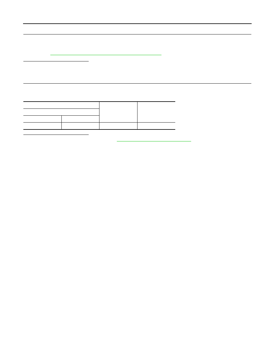
Check voltage between A/C auto amp. harness connector and ground. 

Is the inspection result normal?

YES

>> Replace A/C auto amp. Refer to 

HAC-79, "Removal and Installation"

.

NO

>> Repair harness or connector between A/C auto amp. and fuse.

+

Voltage

A/C auto amp.

Connector

Terminal

M50

40

Ground

Battery voltage

Revision: 2012 October

2013 Murano CrossCabriolet

DOOR MOTOR

HAC-65

< DTC/CIRCUIT DIAGNOSIS >

[AUTOMATIC AIR CONDITIONING]

C

D

E

F

G

H

J

K

L

M

A

B

HAC

N

O

P

DOOR MOTOR

Diagnosis Procedure

INFOID:0000000008460680

NOTE:
Check this circuit when all of door motors DTC (B2632, B2633, B2634, B2635, B2636, B2637, B2638, B2639,
B263D, B263E, B263F, B2654, B2655, B2661, B2662, and B2663) are detected.

1.

CHECK DOOR MOTOR POWER SUPPLY

1.

Turn ignition switch ON.

2.

Check voltage between intake door motor harness connector and ground.

Is the inspection result normal?

YES

>> GO TO 2.

NO

>> GO TO 7.

2.

CHECK DOOR MOTOR GROUND CIRCUIT FOR OPEN

1.

Turn ignition switch OFF.

2.

Disconnect intake door motor and A/C auto amp. connector.

3.

Check continuity between intake door motor harness connector and ground.

Is the inspection result normal?

YES

>> GO TO 3.

NO

>> Repair harness or connector.

3.

CHECK DOOR MOTOR LAN SIGNAL

1.

Connect A/C auto amp. and intake door motor connector.

2.

Turn ignition switch ON.

3.

Confirm output waveform between A/C auto amp. harness connector and ground using oscilloscope.

Is the inspection result normal?

YES

>> GO TO 4.

NO

>> GO TO 6.

4.

CHECK DOOR MOTOR LAN SIGNAL CIRCUIT FOR OPEN

1.

Turn ignition switch OFF.

2.

Disconnect A/C auto amp. and intake door motor connector.

+

Voltage

(Approx.)

Intake door motor

Connector

Terminal

M304

1

Ground

12 V

Intake door motor

Continuity

Connector

Terminal

M304

2

Ground

Existed

+

Output waveform

A/C auto amp.

Connector

Terminal

M50

5

Ground

SJIA1453J

Revision: 2012 October

2013 Murano CrossCabriolet

HAC-66

< DTC/CIRCUIT DIAGNOSIS >

[AUTOMATIC AIR CONDITIONING]

DOOR MOTOR

3.

Check continuity between A/C auto amp. harness connector and intake door motor harness connector.

Is the inspection result normal?

YES

>> GO TO 5.

NO

>> Repair harness or connector.

5.

CHECK INTERMITTENT INCIDENT

Check intermittent incident. Refer to 

GI-40, "Intermittent Incident"

.

>> INSPECTION END

6.

CHECK DOOR MOTOR LAN SIGNAL CIRCUIT FOR SHORT

1.

Turn ignition switch OFF.

2.

Disconnect following connectors.

-

A/C auto amp.

-

Air mix door motor LH

-

Air mix door motor RH

-

Mode door motor

-

Intake door motor

3.

Check continuity between A/C auto amp. harness connector and ground.

Is the inspection result normal?

YES

>> Replace A/C auto amp. Refer to 

HAC-79, "Removal and Installation"

.

NO

>> Repair harness or connector.

7.

CHECK DOOR MOTOR POWER SUPPLY CIRCUIT FOR OPEN

1.

Turn ignition switch OFF.

2.

Disconnect intake door motor and A/C auto amp. connector.

3.

Check continuity between intake door motor harness connector and A/C auto amp. harness connector.

Is the inspection result normal?

YES

>> GO TO 8.

NO

>> Repair harness or connector.

8.

CHECK DOOR MOTOR POWER SUPPLY CIRCUIT FOR SHORT

1.

Disconnect following connectors.

-

A/C auto amp.

-

Air mix door motor LH

-

Air mix door motor RH

-

Mode door motor

2.

Check continuity between A/C auto amp. harness connector and ground.

A/C auto amp.

Intake door motor

Continuity

Connector

Terminal

Connector

Terminal

M50

10

M304

3

Existed

A/C auto amp.

Continuity

Connector

Terminal

M50

10

Ground

Not existed

Intake door motor

A/C auto amp.

Continuity

Connector

Terminal

Connector

Terminal

M304

1

M50

11

Existed

A/C auto amp.

Continuity

Connector

Terminal

M50

11

Ground

Not existed

Revision: 2012 October

2013 Murano CrossCabriolet

DOOR MOTOR

HAC-67

< DTC/CIRCUIT DIAGNOSIS >

[AUTOMATIC AIR CONDITIONING]

C

D

E

F

G

H

J

K

L

M

A

B

HAC

N

O

P

Is the inspection result normal?

YES

>> Replace A/C auto amp. Refer to 

HAC-79, "Removal and Installation"

.

NO

>> Repair harness or connector.

Revision: 2012 October

2013 Murano CrossCabriolet

HAC-68

< DTC/CIRCUIT DIAGNOSIS >

[AUTOMATIC AIR CONDITIONING]

BLOWER MOTOR

BLOWER MOTOR

Diagnosis Procedure

INFOID:0000000008460681

1.

CHECK FUSE

1.

Turn ignition switch OFF.

2.

Check 15A fuse [No. 21 and 22, located in fuse block (J/B)]. 
NOTE:
Refer to 

PG-33, "Fuse, Connector and Terminal Arrangement"

Is the inspection result normal?

YES

>> GO TO 2.

NO

>> Replace the blown fuse after repairing the affected circuit if a fuse is blown. 

2.

CHECK BLOWER MOTOR POWER SUPPLY

1.

Disconnect blower motor connector.

2.

Turn ignition switch ON.

3.

Check voltage between blower motor harness connector and ground. 

Is the inspection result normal?

YES

>> GO TO 3.

NO

>> GO TO 6.

3.

CHECK BLOWER MOTOR GROUND CIRCUIT FOR OPEN

1.

Turn ignition switch OFF.

2.

Check continuity between blower motor harness connector and ground. 

Is the inspection result normal?

YES

>> GO TO 4.

NO

>> Repair harness or connector. 

4.

CHECK BLOWER MOTOR CONTROL SIGNAL CIRCUIT FOR OPEN

1.

Disconnect A/C auto amp. connector. 

2.

Check continuity between blower motor harness connector and A/C auto amp. harness connector. 

Is the inspection result normal?

YES

>> GO TO 5.

NO

>> Repair harness or connector.

5.

CHECK BLOWER MOTOR CONTROL SIGNAL

1.

Reconnect blower motor connector and A/C auto amp. connector. 

2.

Turn ignition switch ON.

3.

Operate MODE switch to set air outlet to VENT position.

4.

Change fan speed from Lo to Hi, and check duty ratios between blower motor harness connector and
ground by using an oscilloscope. 

+

Voltage

Blower motor

Connector

Terminal

M98

1

Ground

Battery voltage

Blower motor

Continuity

Connector

Terminal

M98

3

Ground

Existed

Blower motor

A/C auto amp.

Continuity

Connector

Terminal

Connector

Terminal

M98

2

M50

32

Existed

Revision: 2012 October

2013 Murano CrossCabriolet

BLOWER MOTOR

HAC-69

< DTC/CIRCUIT DIAGNOSIS >

[AUTOMATIC AIR CONDITIONING]

C

D

E

F

G

H

J

K

L

M

A

B

HAC

N

O

P

NOTE:
Calculate drive signal duty ratio as shown in the figure.
T2 = Approx. 1.6 ms

Is the inspection result normal?

YES

>> Replace blower motor. Refer to 

VTL-21, "Removal and Installation"

.

NO

>> Replace A/C auto amp. Refer to 

HAC-79, "Removal and Installation"

.

6.

CHECK BLOWER MOTOR POWER SUPPLY CIRCUIT FOR OPEN

1.

Turn ignition switch OFF. 

2.

Disconnect fuse block (J/B) connector. 

3.

Check continuity between fuse block (J/B) harness connector and blower motor harness connector. 

Is the inspection result normal?

YES

>> GO TO 7.

NO

>> Repair harness or connector.

7.

CHECK BLOWER RELAY GROUND CIRCUIT FOR OPEN

Check continuity between fuse block (J/B) harness connector and ground. 

Is the inspection result normal?

YES

>> GO TO 8.

NO

>> Repair harness or connector. 

8.

CHECK BLOWER RELAY

Check blower relay. Refer to 

HAC-70, "Component Inspection (Blower Relay)"

.

Is the inspection result normal?

YES

>> Check blower relay power supply circuit. Refer to 

PG-11, "Wiring Diagram - BATTERY POWER

SUPPLY -"

 and 

PG-27, "Wiring Diagram - IGNITION POWER SUPPLY -"

.

NO

>> Replace blower relay.

Component Inspection (Blower Motor)

INFOID:0000000008460682

1.

CHECK BLOWER MOTOR-I

1.

Remove blower motor. Refer to 

VTL-21, "Removal and Installation"

.

Blower motor

Condition

Duty ratio

(Approx.)

Connector

Terminal

Fan speed (manual)

VENT mode

M98

2

1st

25 %

2nd

33 %

3rd

41 %

4th

51 %

5th

61 %

6th

69 %

7th

81 %

JPLIA1210GB

Fuse block (J/B)

Blower motor

Continuity

Connector

Terminal

Connector

Terminal

M1

3A

M98

3

Existed

8A

Fuse block (J/B)

Continuity

Connector

Terminal

M3

7C

Ground

Existed

Revision: 2012 October

2013 Murano CrossCabriolet

HAC-70

< DTC/CIRCUIT DIAGNOSIS >

[AUTOMATIC AIR CONDITIONING]

BLOWER MOTOR

2.

Check that there is not any mixing foreign object in the blower motor. 

Is the inspection result normal?

YES

>> GO TO 2.

NO

>> Replace blower motor. Refer to 

VTL-21, "Removal and Installation"

.

2.

CHECK BLOWER MOTOR-II

Check that there is not breakage or damage in the blower motor. 

Is the inspection result normal?

YES

>> GO TO 3.

NO

>> Replace blower motor. Refer to 

VTL-21, "Removal and Installation"

.

3.

CHECK BLOWER MOTOR-III

Check that blower motor turns smoothly. 
Is the inspection result normal?

YES

>> INSPECTION END

NO

>> Replace blower motor. Refer to 

VTL-21, "Removal and Installation"

.

Component Inspection (Blower Relay)

INFOID:0000000008460683

1.

CHECK BLOWER RELAY

1.

Remove blower relay. Refer to 

PG-33, "Fuse, Connector and Terminal Arrangement"

.

2.

Check continuity between blower relay terminal 3 and 5 when
voltage is supplied between terminal 1 and 2. 

Is the inspection result normal?

YES

>> INSPECTION END

NO

>> Replace blower relay.

Terminal

Voltage

Continuity

3

5

ON

Existed

OFF

Not existed

JSIIA1551ZZ

Revision: 2012 October

2013 Murano CrossCabriolet

MAGNET CLUTCH

HAC-71

< DTC/CIRCUIT DIAGNOSIS >

[AUTOMATIC AIR CONDITIONING]

C

D

E

F

G

H

J

K

L

M

A

B

HAC

N

O

P

MAGNET CLUTCH

Component Function Check

INFOID:0000000008460684

1.

CHECK MAGNET CLUTCH OPERATION

Perform auto active test of IPDM E/R. Refer to 

PCS-10, "Diagnosis Description"

Does it operate normally?

YES

>> INSPECTION END

NO

>> Refer to 

HAC-71, "Diagnosis Procedure"

.

Diagnosis Procedure

INFOID:0000000008460685

1.

CHECK MAGNET CLUTCH

1.

Turn ignition switch OFF. 

2.

Disconnect compressor connector. 

3.

Directly apply battery voltage to the magnet clutch. Check for operation visually and by sound. 

Does it operate normally?

YES

>> GO TO 2.

NO

>> GO TO 4.

2.

CHECK FUSE

Check 10A fuse (No. 49, located in IPDM E/R). 
NOTE:
Refer to 

PG-35, "Fuse, Connector and Terminal Arrangement"

.

Is the inspection result normal?

YES

>> GO TO 3.

NO

>> Replace the blown fuse after repairing the affected circuit if a fuse is blown. 

3.

CHECK MAGNET CLUTCH POWER SUPPLY CIRCUIT FOR OPEN

1.

Disconnect IPDM E/R connector.

2.

Check continuity between IPDM E/R harness connector and compressor harness connector. 

Is the inspection result normal?

YES

>> Replace IPDM E/R. Refer to 

PCS-31, "Removal and Installation"

.

NO

>> Repair harness or connector.

4.

CHECK MAGNET CLUTCH GROUND CIRCUIT FOR OPEN

Check continuity between compressor harness connector and ground. 

Is the inspection result normal?

YES

>> Replace magnet clutch. Refer to 

HA-31, "MAGNET CLUTCH : Removal and Installation of Com-

pressor Clutch"

.

NO

>> Repair harness or connector. 

IPDM E/R

Compressor

Continuity

Connector

Terminal

Connector

Terminal

F12

48

F18

1

Existed

Compressor

Continuity

Connector

Terminal

F18

2

Ground

Existed

Revision: 2012 October

2013 Murano CrossCabriolet

HAC-72

< SYMPTOM DIAGNOSIS >

[AUTOMATIC AIR CONDITIONING]

AUTOMATIC AIR CONDITIONING SYSTEM

SYMPTOM DIAGNOSIS

AUTOMATIC AIR CONDITIONING SYSTEM

Symptom Table

INFOID:0000000008460686

NOTE:
Perform self-diagnoses with CONSULT before performing the symptom diagnosis. If any DTC is detected,
perform the corresponding diagnosis.

Symptom

Corresponding malfunction part

Check item/Reference

• Air conditioning does not ac-

tivate.

• Air conditioning cannot be 

controlled.

• Operation status of air condi-

tioning is not indicated on 
display.

Fail-safe activates

Multi AV system

• BOSE audio without naviga-

tion: 

AV-95, "Symptom Table"

• BOSE audio with navigation: 

AV-224, "Symptom Table"

Fail-safe does not acti-
vate

• A/C auto amp. ignition power supply 

circuit and ACC power supply circuit

• A/C auto amp.

HAC-63, "A/C AUTO AMP. : Di-
agnosis Procedure"

• Memory function does not operate normally.
• The setting is not maintained. (It returns to initial condi-

tion)

• A/C auto amp. battery power supply 

circuit

• A/C auto amp.

HAC-63, "A/C AUTO AMP. : Di-
agnosis Procedure"

Discharge air temperature (driver side) does not change.

Air mix door motor (driver side) system 
installation condition

Check air mix door motor (driver 
side) system is properly in-
stalled. Refer to 

HAC-86, "Ex-

ploded View"

.

Discharge air temperature (passenger side) does not 
change.

Air mix door motor (passenger side) 
system installation condition

Check air mix door motor (pas-
senger side) system is properly 
installed. Refer to 

HAC-86, "Ex-

ploded View"

.

Air outlet does not change.

Mode door motor system installation 
condition

Check mode door motor system 
is properly installed. Refer to 

HAC-86, "Exploded View"

.

Air inlet does not change.

Intake door motor system installation 
condition

Check intake door motor system 
is properly installed. Refer to 

HAC-86, "Exploded View"

.

Blower motor does not operate.

• Blower motor power supply circuit.
• Blower motor control signal circuit
• Blower  motor
• A/C auto amp.

HAC-68, "Diagnosis Procedure"


Compressor does not operate. 

• Magnet clutch
• The circuit between magnet clutch 

and IPDM E/R

• IPDM E/R (A/C relay)
• The circuit between ECM and refrig-

erant pressure sensor

• Refrigerant pressure sensor
• A/C auto amp. output signal (A/C 

ON signal and blower fan ON signal) 

• A/C auto amp.

HAC-77, "Diagnosis Procedure"

• Insufficient cooling
• No cool air comes out. (Air flow volume is normal.)

• Magnet clutch control system
• Drive belt slipping
• Cooler cycle
• Air leakage from each duct
• A/C auto amp. connection recogni-

tion signal circuit

• Temperature setting trimmer

HAC-74, "Diagnosis Procedure"

Revision: 2012 October

2013 Murano CrossCabriolet

AUTOMATIC AIR CONDITIONING SYSTEM

HAC-73

< SYMPTOM DIAGNOSIS >

[AUTOMATIC AIR CONDITIONING]

C

D

E

F

G

H

J

K

L

M

A

B

HAC

N

O

P

• Insufficient heating
• No warm air comes out. (Air flow volume is normal.)

• Engine cooling system
• Heater hose
• Heater core
• Air leakage from each duct
• Temperature setting trimmer

HAC-76, "Diagnosis Procedure"

Noise is heard when the air 
conditioning operates.

During compressor op-
eration

Cooler cycle 

HA-28, "Symptom Table"

During blower motor op-
eration

• Mixing any foreign object in blower 

motor

• Blower motor fan breakage
• Blower motor rotation inferiority

HAC-69, "Component Inspec-
tion (Blower Motor)"

Symptom

Corresponding malfunction part

Check item/Reference

Revision: 2012 October

2013 Murano CrossCabriolet

HAC-74

< SYMPTOM DIAGNOSIS >

[AUTOMATIC AIR CONDITIONING]

INSUFFICIENT COOLING

INSUFFICIENT COOLING

Description

INFOID:0000000008460687

Symptom

• Insufficient cooling
• No cool air comes out. (Air flow volume is normal.)

Diagnosis Procedure

INFOID:0000000008460688

NOTE:
Perform self-diagnoses with CONSULT before performing symptom diagnosis. If any DTC is detected, per-
form the corresponding diagnosis.

1.

CHECK MAGNET CLUTCH OPERATION

1.

Turn ignition switch ON.

2.

Operate fan control dial.

3.

Press A/C switch.

4.

Check that A/C indicator turns ON. Check visually and by sound that compressor operates.

5.

Press A/C switch again.

6.

Check that A/C indicator turns OFF. Check that compressor stops.

Is the inspection result normal?

YES

>> GO TO 2.

NO

>> Perform diagnosis of “COMPRESSOR DOES NOT OPERATE” in “SYMPTOM DIAGNOSIS”.

Refer to 

HAC-77, "Diagnosis Procedure"

.

2.

CHECK DRIVE BELT

Check tension of drive belt. Refer to 

EM-14, "Checking"

.

Is the inspection result normal?

YES

>> GO TO 3.

NO

>> Adjust or replace drive belt depending on the inspection results.

3.

CHECK REFRIGERANT CYCLE PRESSURE

Connect recovery/recycling recharging equipment to the vehicle and perform pressure inspection with gauge.
Refer to 

HA-26, "Symptom Table"

.

Is the inspection result normal?

YES

>> GO TO 4.

NO

>> Repair or replace parts depending on the inspection results.

4.

CHECK AIR LEAKAGE FROM EACH DUCT

Check duct and nozzle, etc. of the air conditioning system for leakage.

Is the inspection result normal?

YES

>> GO TO 5.

NO

>> Repair or replace parts depending on the inspection results.

5.

CHECK AMBIENT TEMPERATURE DISPLAY

Check that there is not much difference between actual ambient temperature and indicated temperature on
information display in combination meter.

Is the inspection result normal?

YES

>> GO TO 6.

NO

>> Perform diagnosis for the A/C auto amp. connection recognition signal circuit. Refer to 

MWI-59,

"Diagnosis Procedure"

.

6.

CHECK SETTING OF TEMPERATURE SETTING TRIMMER

1.

Check setting value of temperature setting trimmer. Refer to 

HAC-35, "Temperature Setting Trimmer"

2.

Check that temperature setting trimmer is set to “+ direction”. 
NOTE:
The control temperature can be set by setting of the temperature setting trimmer.

Revision: 2012 October

2013 Murano CrossCabriolet

INSUFFICIENT COOLING

HAC-75

< SYMPTOM DIAGNOSIS >

[AUTOMATIC AIR CONDITIONING]

C

D

E

F

G

H

J

K

L

M

A

B

HAC

N

O

P

3.

Set difference between the set temperature and control temperature to “0”.

Is inspection result normal?

YES

>> INSPECTION END

NO

>> Replace A/C auto amp. Refer to 

HAC-79, "Removal and Installation"

.

Revision: 2012 October

2013 Murano CrossCabriolet

HAC-76

< SYMPTOM DIAGNOSIS >

[AUTOMATIC AIR CONDITIONING]

INSUFFICIENT HEATING

INSUFFICIENT HEATING

Description

INFOID:0000000008460689

Symptom

• Insufficient heating
• No warm air comes out. (Air flow volume is normal.)

Diagnosis Procedure

INFOID:0000000008460690

NOTE:
Perform self-diagnoses with CONSULT before performing symptom diagnosis. If any DTC is detected, per-
form the corresponding diagnosis.

1.

CHECK COOLING SYSTEM

1.

Check engine coolant level and check for leakage. Refer to 

CO-8, "Inspection"

.

2.

Check radiator cap. Refer to the 

CO-12, "RADIATOR CAP : Inspection"

.

3.

Check water flow sounds of the engine coolant. Refer to 

CO-9, "Refilling"

.

Is the inspection result normal?

YES

>> GO TO 2.

NO

>> Refill engine coolant and repair or replace the parts depending on the inspection results.

2.

CHECK HEATER HOSE

Check installation of heater hose by visually or touching.

Is the inspection result normal?

YES

>> GO TO 3.

NO

>> Repair or replace parts depending on the inspection results.

3.

CHECK HEATER CORE

1.

Check temperature of inlet hose and outlet hose of heater core.

2.

Check that inlet side of heater core is hot and the outlet side is slightly lower than/almost equal to the inlet
side.

CAUTION:

Always perform the temperature inspection in a short period of time because the engine coolant
temperature is very hot.

Is the inspection result normal?

YES

>> GO TO 4.

NO

>> Replace heater core. Refer to 

HA-49, "HEATER CORE : Removal and Installation"

.

4.

CHECK AIR LEAKAGE FROM EACH DUCT

Check duct and nozzle, etc. of the air conditioning for air leakage.

Is the inspection result normal?

YES

>> GO TO 5.

NO

>> Repair or replace parts depending on the inspection results.

5.

CHECK SETTING OF TEMPERATURE SETTING TRIMMER

1.

Check setting value of temperature setting trimmer. Refer to 

HAC-35, "Temperature Setting Trimmer"

2.

Check that temperature setting trimmer is set to “

 direction”. 

NOTE:
The control temperature can be set by the temperature setting trimmer.

3.

Set difference between the set temperature and control temperature to “0”.

Are the symptoms solved?

YES

>> INSPECTION END

NO

>> Replace A/C auto amp. Refer to 

HAC-79, "Removal and Installation"

.

Revision: 2012 October

2013 Murano CrossCabriolet

COMPRESSOR DOES NOT OPERATE

HAC-77

< SYMPTOM DIAGNOSIS >

[AUTOMATIC AIR CONDITIONING]

C

D

E

F

G

H

J

K

L

M

A

B

HAC

N

O

P

COMPRESSOR DOES NOT OPERATE

Description

INFOID:0000000008460691

SYMPTOM

Compressor does not operate. 

Diagnosis Procedure

INFOID:0000000008460692

NOTE:
• Perform self-diagnoses with CONSULT before performing symptom diagnosis. If any DTC is detected, per-

form the corresponding diagnosis.

• Check that refrigerant is enclosed in cooler cycle normally. If refrigerant amount is shortage from proper

amount, perform the inspection of refrigerant leakage.

1.

CHECK MAGNET CLUTCH OPERATION

Check magnet clutch. Refer to 

HAC-71, "Component Function Check"

Does it operate normally?

YES

>> GO TO 2.

NO

>> Repair or replace malfunctioning parts.

2.

CHECK REFRIGERANT PRESSURE SENSOR

Check refrigerant pressure sensor. Refer to 

EC-417, "Component Function Check"

.

Is the inspection result normal?

YES

>> GO TO 3.

NO

>> Repair or replace malfunctioning parts.

3.

CHECK A/C AUTO AMP. OUTPUT SIGNAL

With CONSULT

1.

Select “DATA MONITOR” mode of “ECM” using CONSULT.

2.

Select “AIR COND SIG” and “HEATER FAN SW”, and check status under the following conditions.

Is the inspection result normal?

YES

>> Replace IPDM E/R. Refer to 

PCS-31, "Removal and Installation"

.

NO

>> Replace A/C auto amp. Refer to 

HAC-79, "Removal and Installation"

.

Monitor item

Condition

Status

AIR COND SIG

A/C switch

OFF (A/C indicator: OFF)

Off

ON (A/C indicator: ON)

On

HEATER FAN SW

Blower motor

OFF

Off

ON

On

Revision: 2012 October

2013 Murano CrossCabriolet

HAC-78

< REMOVAL AND INSTALLATION >

[AUTOMATIC AIR CONDITIONING]

PRESET SWITCH

REMOVAL AND INSTALLATION

PRESET SWITCH

Exploded View

INFOID:0000000008460693

DISASSEMBLY

Removal and Installation

INFOID:0000000008460694

REMOVAL

Remove preset switch. Refer to the following.
• Refer to 

AV-112, "Removal and Installation"

. (BOSE AUDIO WITHOUT NAVIGATION)

• Refer to 

AV-246, "Removal and Installation"

. (BOSE AUDIO WITH NAVIGATION)

INSTALLATION

Install in the reverse order of removal.

1.

Preset switch

2.

Cluster lid C

JPNIA0790ZZ

Revision: 2012 October

2013 Murano CrossCabriolet

A/C AUTO AMP.

HAC-79

< REMOVAL AND INSTALLATION >

[AUTOMATIC AIR CONDITIONING]

C

D

E

F

G

H

J

K

L

M

A

B

HAC

N

O

P

A/C AUTO AMP.

Exploded View

INFOID:0000000008460695

DISASSEMBLY

Removal and Installation

INFOID:0000000008460696

REMOVAL

1.

Remove AV control unit. Refe to the following.
• Refer to 

AV-102, "Removal and Installation"

. (BOSE AUDIO WITHOUT NAVIGATION)

• Refer to 

AV-236, "Removal and Installation"

. (BOSE AUDIO WITH NAVIGATION)

2.

Remove fixing screws (A), and then remove A/C auto amp. (1).

INSTALLATION

Install in the reverse order of removal.

JPIIA0553ZZ

1.

AV control unit

2.

Bracket LH

3.

A/C auto amp.

4.

Bracket RH

JPIIA0554ZZ

Revision: 2012 October

2013 Murano CrossCabriolet


Content      ..     47      48      49      50     ..