Murano Cross Cabriolet Z51 (2013 year). Manual - part 52
INL-20
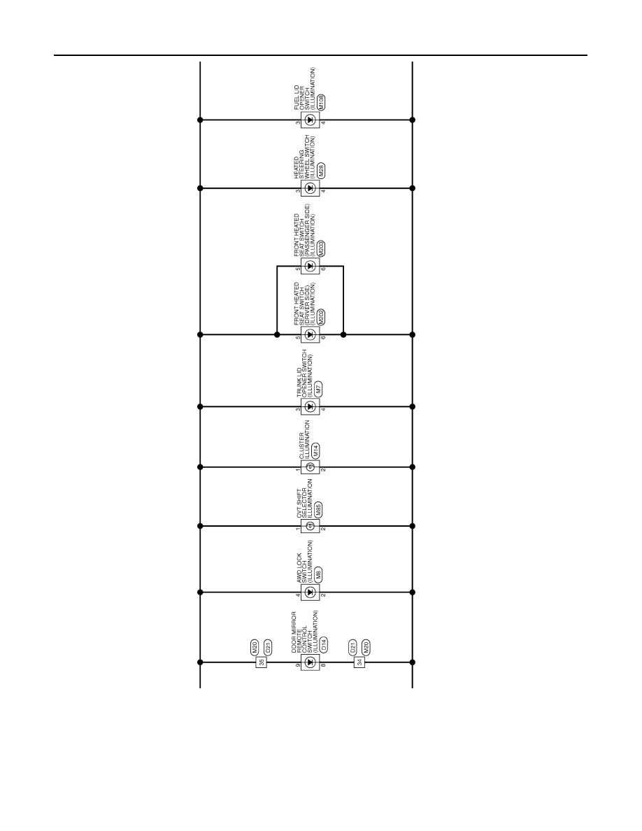
< WIRING DIAGRAM >
ILLUMINATION
JRLWC2942GB
Revision: 2012 October
2013 Murano CrossCabriolet
|
|
|
INL-20 < WIRING DIAGRAM > ILLUMINATION JRLWC2942GB Revision: 2012 October 2013 Murano CrossCabriolet |