Murano Cross Cabriolet Z51 (2013 year). Manual - part 38
FL-16
< REMOVAL AND INSTALLATION >
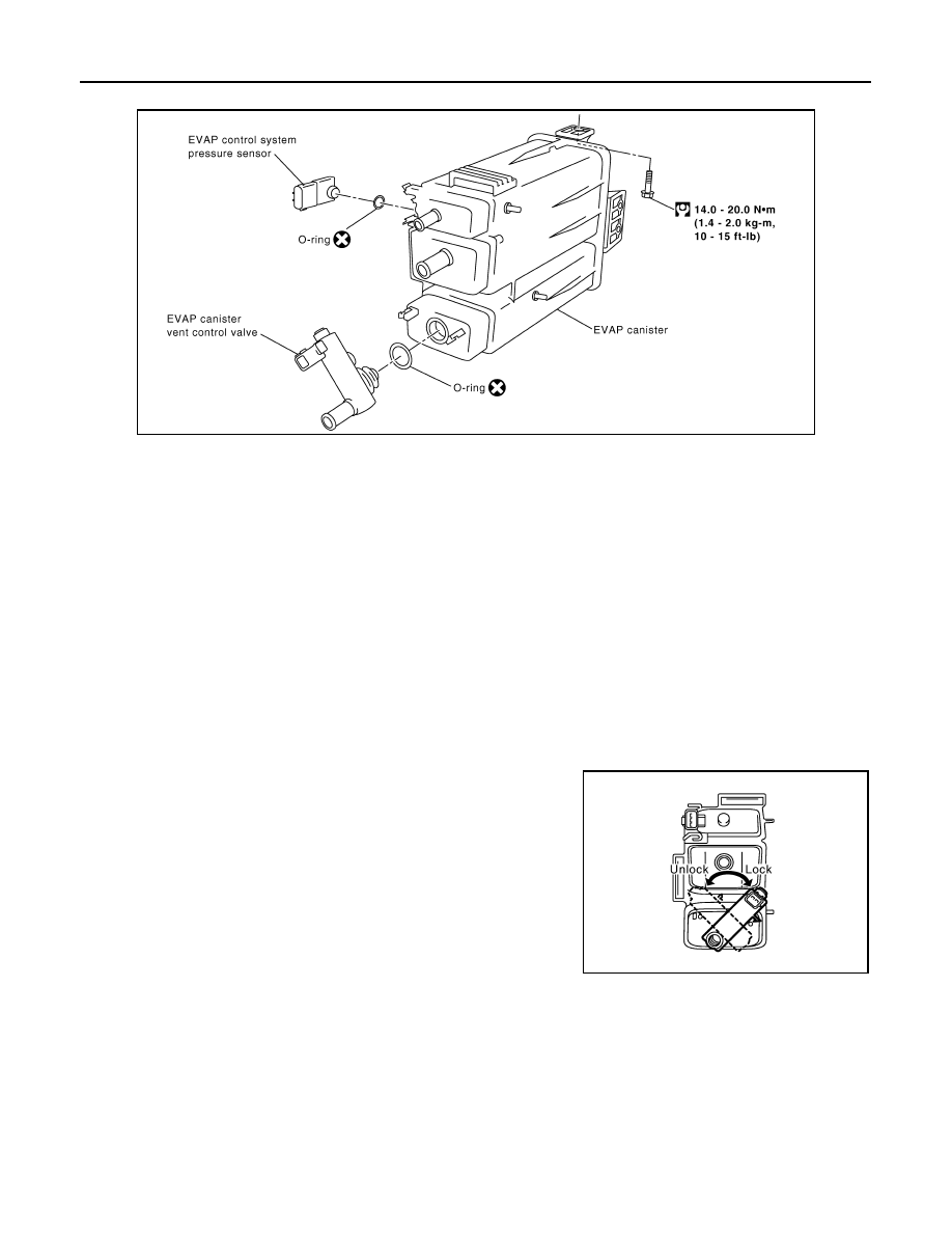
EVAP CANISTER
Exploded View
INFOID:0000000008462085
Removal and Installation
INFOID:0000000008462086
REMOVAL
1.
Lift up the vehicle.
2.
Remove EVAP canister fixing bolt.
3.
Remove EVAP canister.
NOTE:
The EVAP canister vent control valve and EVAP canister system pressure sensor can be removed without
removing the EVAP canister.
INSTALLATION
Install in the reverse order of removal.
NOTE:
Tighten EVAP canister fixing bolt to the specified torque.
DISASSEMBLY
1.
Turn EVAP canister vent control valve counterclockwise.
2.
Remove the EVAP canister vent control valve.
ASSEMBLY
CAUTION:
Always replace O-ring with a new one.
Assemble in the reverse order of disassembly.
PBIB1383E
PBIB1384E
Revision: 2012 October
2013 Murano CrossCabriolet