Nissan Murano Z51 (2008 year). Manual - part 150
EC-216
< COMPONENT DIAGNOSIS >
[VQ35DE]
P0138, P0158 HO2S2
14.
REPLACE HEATED OXYGEN SENSOR 2
Replace malfunctioning heated oxygen sensor 2.
CAUTION:
• Discard any heated oxygen sensor which has been dropped from a height of more than 0.5 m (19.7
in) onto a hard surface such as a concrete floor; use a new one.
• Before installing new oxygen sensor, clean exhaust system threads using Oxygen Sensor Thread
Cleaner [commercial service tool (J-43897-18 or J-43897-12)] and approved anti-seize lubricant
(commercial service tool).
>> INSPECTION END
15.
CHECK INTERMITTENT INCIDENT
GI-40, "Intermittent Incident"
>> INSPECTION END
Component Inspection
INFOID:0000000003624898
1.
INSPECTION START
Will CONSULT-III be used?
Will CONSULT-III be used?
YES
>> GO TO 2.
NO
>> GO TO 3.
2.
CHECK HEATED OXYGEN SENSOR 2
With CONSULT-III
1.
Turn ignition switch ON and select “DATA MONITOR” mode with CONSULT-III.
2.
Start engine and warm it up to the normal operating temperature.
3.
Turn ignition switch OFF and wait at least 10 seconds.
4.
Start engine and keep the engine speed between 3,500 and 4,000 rpm for at least 1 minute under no load.
5.
Let engine idle for 1 minute.
6.
Select “FUEL INJECTION” in “ACTIVE TEST” mode, and select “HO2S2 (B1)/(B2)” as the monitor item
with CONSULT-III.
7.
Check “HO2S2 (B1)/(B2)” at idle speed when adjusting “FUEL INJECTION” to
±
25%.
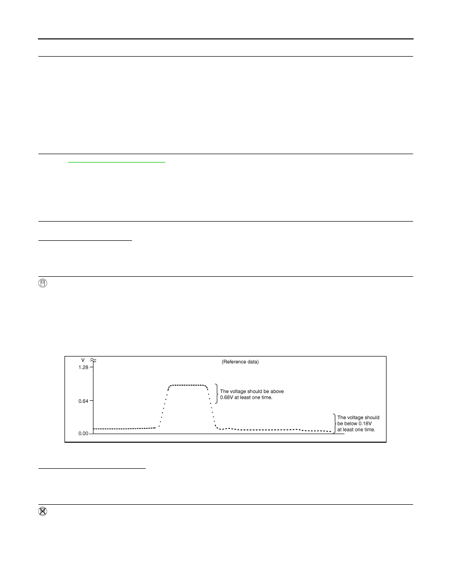
“HO2S2 (B1)/(B2)” should be above 0.68 V at least once when the “FUEL INJECTION” is + 25%.
“HO2S2 (B1)/(B2)” should be below 0.18 V at least once when the “FUEL INJECTION” is
−
25%.
Is the inspection result normal?
YES
>> INSPECTION END
NO
>> GO TO 6.
3.
CHECK HEATED OXYGEN SENSOR 2-I
Without CONSULT-III
1.
Start engine and warm it up to the normal operating temperature.
2.
Turn ignition switch OFF and wait at least 10 seconds.
3.
Start engine and keep the engine speed between 3,500 and 4,000 rpm for at least 1 minute under no load.
4.
Let engine idle for 1 minute.
5.
Check the voltage between ECM harness connector terminals under the following conditions.
PBIB3458E
Revision: 2008 October
2009 Murano