Nissan Murano Z51 (2008 year). Manual - part 149


  Index      Manuals     Nissan Murano Z51 (2008 year) - Service and Repair Manual


Search            copyright infringement  


Content      ..     147      148      149      150     ..


Nissan Murano Z51 (2008 year). Manual - part 149


EC-200

< COMPONENT DIAGNOSIS >

[VQ35DE]

P0133, P0153 A/F SENSOR 1

>> Repair or replace malfunctioning part.

7.

PERFORM DTC CONFIRMATION PROCEDURE-IV

1.

Turn ignition switch OFF and wait at least 10 seconds.

2.

Turn ignition switch ON.

3.

Turn ignition switch OFF and wait at least 10 seconds.

4.

Start engine and keep the engine speed between 3,500 and 4,000 rpm for at least 1minute under no load.

5.

Let engine idle for 1 minute.

6.

Increase the engine speed up to between 4,000 and 5,000 rpm and maintain that speed for 10 seconds.

7.

Fully release accelerator pedal and then let engine idle for approximately 1 minute.

8.

Check 1st trip DTC.

Is 1st trip DTC detected?

YES

>> Go to 

EC-200, "Diagnosis Procedure"

.

NO

>> INSPECTION END

Diagnosis Procedure

INFOID:0000000003387999

1.

CHECK GROUND CONNECTION

1.

Turn ignition switch OFF.

2.

Check ground connection E38. Refer to Ground Inspection in 

GI-43, "Circuit Inspection"

.

Is the inspection result normal?

YES

>> GO TO 2.

NO

>> Repair or replace ground connection.

2.

RETIGHTEN A/F SENSOR 1

Loosen and retighten the A/F sensor 1. Refer to 

EM-34, "Removal and Installation"

.

>> GO TO 3.

3.

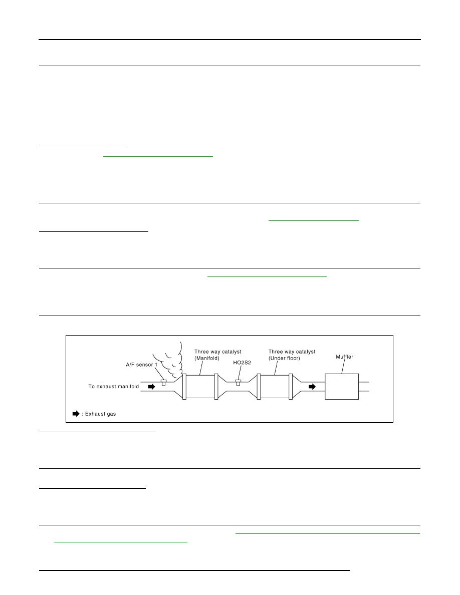
CHECK EXHAUST GAS LEAKAGE

1.

Start engine and run it at idle.

2.

Listen for an exhaust gas leakage before three way catalyst (manifold).

Is exhaust gas leakage detected?

YES

>> Repair or replace malfunctioning part.

NO

>> GO TO 4.

4.

CHECK FOR INTAKE AIR LEAKAGE

Listen for an intake air leakage after the mass air flow sensor.
Is intake air leakage detected?

YES

>> Repair or replace malfunctioning part.

NO

>> GO TO 5.

5.

CLEAR MIXTURE RATIO SELF-LEARNING VALUE

1.

Clear the mixture ratio self-learning value. Refer to 

EC-19, "MIXTURE RATIO SELF-LEARNING VALUE

CLEAR : Special Repair Requirement"

.

2.

Run engine for at least 10 minutes at idle speed.

3.

Check 1st trip DTC.

Is the 1st trip DTC P0171, P0172, P0174 or P0175 detected? Is it difficult to start engine?

PBIB1216E

Revision: 2008 October

2009 Murano

P0133, P0153 A/F SENSOR 1

EC-201

< COMPONENT DIAGNOSIS >

[VQ35DE]

C

D

E

F

G

H

I

J

K

L

M

A

EC

N

P

O

YES

>> Perform trouble diagnosis for DTC P0171, P0174 or P0172, P0175. Refer to 

EC-226, "DTC Logic"

or 

EC-231, "DTC Logic"

.

NO

>> GO TO 6.

6.

CHECK AIR FUEL RATIO (A/F) SENSOR 1 POWER SUPPLY CIRCUIT

1.

Turn ignition switch OFF.

2.

Disconnect A/F sensor 1 harness connector.

3.

Turn ignition switch ON.

4.

Check the voltage between A/F sensor 1 harness connector and ground.

Is the inspection result normal?

YES

>> GO TO 8.

NO

>> GO TO 7.

7.

DETECT MALFUNCTIONING PART

Check the following.
• IPDM E/R harness connector F12
• 15 A fuse (No. 46)
• Harness for open or short between A/F sensor 1 and IPDM E/R

>> Repair or replace harness or connectors.

8.

CHECK A/F SENSOR 1 INPUT SIGNAL CIRCUIT FOR OPEN AND SHORT

1.

Turn ignition switch OFF.

2.

Disconnect ECM harness connector.

3.

Check the continuity between A/F sensor 1 harness connector and ECM harness connector.

4.

Check the continuity between A/F sensor 1 harness connector and ground, or ECM harness connector
ground.

DTC

A/F sensor 1

Ground

Voltage

Bank

Connector

Terminal

P0133

1

F27

4

Ground

Battery voltage

P0153

2

F64

4

DTC

A/F sensor 1

ECM

Continuity

Bank

Connector

Terminal

Connector

Terminal

P0133

1

F27

1

F8

45

Existed

2

49

P0153

2

F64

1

53

2

57

DTC

A/F sensor 1

Ground

Continuity

Bank

Connector

Terminal

P0133

1

F27

1

Ground

Not existed

2

P0153

2

F64

1

2

Revision: 2008 October

2009 Murano

EC-202

< COMPONENT DIAGNOSIS >

[VQ35DE]

P0133, P0153 A/F SENSOR 1

5.

Also check harness for short to power.

Is the inspection result normal?

YES

>> GO TO 9.

NO

>> Repair open circuit, short to ground or short to power in harness or connectors.

9.

CHECK AIR FUEL RATIO (A/F) SENSOR 1 HEATER

Refer to 

EC-147, "Component Inspection"

.

Is the inspection result normal?

YES

>> GO TO 10.

NO

>> GO TO 13.

10.

CHECK MASS AIR FLOW SENSOR

Refer to 

EC-159, "Component Inspection"

.

Is the inspection result normal?

YES

>> GO TO 11.

NO

>> Replace mass air flow sensor.

11.

CHECK PCV VALVE

Refer to 

EC-462, "Component Inspection"

.

Is the inspection result normal?

YES

>> GO TO 12.

NO

>> Repair or replace PCV valve.

12.

CHECK INTERMITTENT INCIDENT

Perform 

GI-40, "Intermittent Incident"

.

Is the inspection result normal?

YES

>> GO TO 13.

NO

>> Repair or replace malfunctioning part.

13.

REPLACE AIR FUEL RATIO (A/F) SENSOR 1

Replace malfunctioning air fuel ratio (A/F) sensor 1.

CAUTION:

• Discard any A/F sensor which has been dropped from a height of more than 0.5 m (19.7 in) onto a

hard surface such as a concrete floor; use a new one.

• Before installing new A/F sensor, clean exhaust system threads using Oxygen Sensor Thread

Cleaner [commercial service tool (J-43897-18 or J-43897-12)] and approved anti-seize lubricant
(commercial service tool).

>> INSPECTION END

DTC

ECM

Ground

Continuity

Connector

Terminal

P0133

F8

45

Ground

Not existed

49

P0153

53

57

Revision: 2008 October

2009 Murano

P0137, P0157 HO2S2

EC-203

< COMPONENT DIAGNOSIS >

[VQ35DE]

C

D

E

F

G

H

I

J

K

L

M

A

EC

N

P

O

P0137, P0157 HO2S2

Description

INFOID:0000000003388000

The heated oxygen sensor 2, after three way catalyst (manifold),
monitors the oxygen level in the exhaust gas on each bank.
Even if switching characteristics of the air fuel ratio (A/F) sensor 1
are shifted, the air-fuel ratio is controlled to stoichiometric, by the sig-
nal from the heated oxygen sensor 2.
This sensor is made of ceramic zirconia. The zirconia generates volt-
age from approximately 1 V in richer conditions to 0 V in leaner con-
ditions.
Under normal conditions the heated oxygen sensor 2 is not used for
engine control operation.

DTC Logic

INFOID:0000000003388001

DTC DETECTION LOGIC

The heated oxygen sensor 2 has a much longer switching time
between rich and lean than the air fuel ratio (A/F) sensor 1. The oxy-
gen storage capacity of the three way catalyst (manifold) causes the
longer switching time. To judge the malfunctions of heated oxygen
sensor 2, ECM monitors whether the maximum voltage of the sensor
is sufficiently high during various driving conditions such as fuel-cut.

DTC CONFIRMATION PROCEDURE

1.

INSPECTION START

Will CONSULT-III be used?

Will CONSULT-III be used?

YES

>> GO TO 2.

NO

>> GO TO 5.

2.

PRECONDITIONING

If DTC confirmation Procedure has been previously conducted, always perform the following before conduct-
ing the next test.
1.

Turn ignition switch OFF and wait at least 10 seconds.

2.

Turn ignition switch ON.

3.

Turn ignition switch OFF and wait at least 10 seconds.

TESTING CONDITION:
For better results, perform “DTC WORK SUPPORT” at a temperature of 0 to 30

°

C (32 to 86

°

F).

>> GO TO 3.

SEF327R

SEF259VA

DTC No.

Trouble diagnosis name

DTC detecting condition

Possible cause

P0137

Heated oxygen sensor 2 
(bank 1) circuit low volt-
age

The maximum voltage from the sensor does not 
reach the specified voltage.

• Harness or connectors

(The sensor circuit is open or shorted)

• Heated oxygen sensor 2
• Fuel pressure
• Fuel injector
• Intake air leakage

P0157

Heated oxygen sensor 2 
(bank 2) circuit low volt-
age

Revision: 2008 October

2009 Murano

EC-204

< COMPONENT DIAGNOSIS >

[VQ35DE]

P0137, P0157 HO2S2

3.

PERFORM DTC CONFIRMATION PROCEDURE

With CONSULT-III

1.

Turn ignition switch ON and select “DATA MONITOR” mode with CONSULT-III.

2.

Start engine and warm it up to the normal operating temperature.

3.

Turn ignition switch OFF and wait at least 10 seconds.

4.

Turn ignition switch ON.

5.

Turn ignition switch OFF and wait at least 10 seconds.

6.

Start engine and keep the engine speed between 3,500 and 4,000 rpm for at least 1 minute under no load.

7.

Let engine idle for 1 minute.

8.

Check that “COOLAN TEMP/S” indicates more than 70

°

C (158

°

F).

If not, warm up engine and go to next step when “COOLAN TEMP/S” indication reaches 70

°

C (158

°

F).

9.

Open engine hood.

10. Select “HO2S2 (B1) P1147” (for DTC P0137) or “HO2S2 (B2) P1167” (for DTC P0157) of “HO2S2” in

“DTC WORK SUPPORT” mode with CONSULT-III.

11. Follow the instruction of CONSULT-III display.

NOTE:
It will take at most 10 minutes until “COMPLETED” is displayed.

12. Touch “SELF-DIAG RESULTS”.

Which is displayed on CONSULT-III screen?

OK

>> INSPECTION END

NG

>> Go to 

EC-205, "Diagnosis Procedure"

.

CAN NOT BE DIAGNOSED>>GO TO 4.

4.

PERFORM DTC CONFIRMATION PROCEDURE AGAIN

1.

Turn ignition switch OFF and leave the vehicle in a cool place (soak the vehicle).

2.

Perform DTC confirmation procedure again.

>> GO TO 3.

5.

PERFORM COMPONENT FUNCTION CHECK

Perform component function check. Refer to 

EC-204, "Component Function Check"

.

NOTE:
Use component function check to check the overall function of the heated oxygen sensor 2 circuit. During this
check, a 1st trip DTC might not be confirmed.

Is the inspection result normal?

YES

>> INSPECTION END

NO

>> Go to 

EC-205, "Diagnosis Procedure"

.

Component Function Check

INFOID:0000000003388002

1.

PERFORM COMPONENT FUNCTION CHECK-I

Without CONSULT-III

1.

Start engine and warm it up to the normal operating temperature.

2.

Turn ignition switch OFF and wait at least 10 seconds.

3.

Turn ignition switch ON.

4.

Turn ignition switch OFF and wait at least 10 seconds.

5.

Start engine and keep the engine speed between 3,500 and 4,000 rpm for at least 1 minute under no load.

6.

Let engine idle for 1 minute.

7.

Check the voltage between ECM harness connector terminals under the following conditions.

Revision: 2008 October

2009 Murano

P0137, P0157 HO2S2

EC-205

< COMPONENT DIAGNOSIS >

[VQ35DE]

C

D

E

F

G

H

I

J

K

L

M

A

EC

N

P

O

Is the inspection result normal?

YES

>> INSPECTION END

NO

>> GO TO 2.

2.

PERFORM COMPONENT FUNCTION CHECK-II

Check the voltage between ECM harness connector terminals under the following conditions.

Is the inspection result normal?

YES

>> INSPECTION END

NO

>> GO TO 3.

3.

PERFORM COMPONENT FUNCTION CHECK-III

Check the voltage between ECM harness connector terminals under the following conditions.

Is the inspection result normal?

YES

>> INSPECTION END

NO

>> Go to 

EC-205, "Diagnosis Procedure"

.

Diagnosis Procedure

INFOID:0000000003388003

1.

CHECK GROUND CONNECTION

1.

Turn ignition switch OFF.

2.

Check ground connection E38. Refer to Ground Inspection in 

GI-43, "Circuit Inspection"

.

Is the inspection result normal?

YES

>> GO TO 2.

NO

>> Repair or replace ground connection.

DTC

ECM

Condition

Voltage

Connec-

tor

+

Terminal

Terminal

P0137

F8

33

[HO2S2 (bank 1) 

signal]

35

(Sensor 
ground)

Revving up to 4,000 rpm under no 
load at least 10 times

The voltage should be above 0.68 V 
at least once during this procedure.

P0157

34

[HO2S2 (bank 2) 

signal]

DTC

ECM

Condition

Voltage

Connec-

tor

+

Terminal

Terminal

P0137

F8

33

[HO2S2 (bank 1) 

signal]

35

(Sensor 
ground)

Keeping engine at idle for 10 min-
utes

The voltage should be above 0.68 V 
at least once during this procedure.

P0157

34

[HO2S2 (bank 2) 

signal]

DTC

ECM

Condition

Voltage

Connec-

tor

+

Terminal

Terminal

P0137

F8

33

[HO2S2 (bank 1) 

signal]

35

(Sensor 
ground)

Coasting from 80 km/h (50 MPH) 
with selector lever in the D position

The voltage should be above 0.68 V 
at least once during this procedure.

P0157

34

[HO2S2 (bank 2) 

signal]

Revision: 2008 October

2009 Murano

EC-206

< COMPONENT DIAGNOSIS >

[VQ35DE]

P0137, P0157 HO2S2

2.

CLEAR MIXTURE RATIO SELF-LEARNING VALUE

1.

Clear the mixture ratio self-learning value. Refer to 

EC-19, "MIXTURE RATIO SELF-LEARNING VALUE

CLEAR : Special Repair Requirement"

.

2.

Run engine for at least 10 minutes at idle speed.

Is the 1st trip DTC P0171 or P0174 detected? Is it difficult to start engine?

YES

>> Perform trouble diagnosis for DTC P0171 or P0174. Refer to 

EC-226, "DTC Logic"

.

NO

>> GO TO 3.

3.

CHECK HO2S2 GROUND CIRCUIT FOR OPEN AND SHORT

1.

Turn ignition switch OFF.

2.

Disconnect heated oxygen sensor 2 harness connector.

3.

Disconnect ECM harness connector.

4.

Check the continuity between heated oxygen sensor 2 (HO2S2) harness connector and ECM harness
connector.

5.

Also check harness for short to ground and short to power.

Is the inspection result normal?

YES

>> GO TO 4.

NO

>> Repair open circuit, short to ground or short to power in harness or connectors.

4.

CHECK HO2S2 INPUT SIGNAL CIRCUIT FOR OPEN AND SHORT

1.

Check the continuity between HO2S2 harness connector and ECM harness connector.

2.

Check the continuity between HO2S2 harness connector and ground, or ECM harness connector and
ground.

3.

Also check harness for short to power.

Is the inspection result normal?

YES

>> GO TO 5.

NO

>> Repair open circuit, short to ground or short to power in harness or connectors.

5.

CHECK HEATED OXYGEN SENSOR 2

Refer to 

EC-207, "Component Inspection"

.

Is the inspection result normal?

DTC

HO2S2

ECM

Continuity

Bank

Connector

Terminal

Connector

Terminal

P0137

1

F70

1

F8

35

Existed

P0157

2

F71

1

DTC

HO2S2

ECM

Continuity

Bank

Connector

Terminal

Connector

Terminal

P0137

1

F70

4

F8

33

Existed

P0157

2

F71

4

34

DTC

HO2S2

Ground

Continuity

Bank

Connector

Terminal

P0137

1

F70

4

Ground

Not existed

P0157

2

F71

4

DTC

ECM

Ground

Continuity

Connector

Terminal

P0137

F8

33

Ground

Not existed

P0157

34

Revision: 2008 October

2009 Murano

P0137, P0157 HO2S2

EC-207

< COMPONENT DIAGNOSIS >

[VQ35DE]

C

D

E

F

G

H

I

J

K

L

M

A

EC

N

P

O

YES

>> GO TO 7.

NO

>> GO TO 6.

6.

REPLACE HEATED OXYGEN SENSOR 2

Replace malfunctioning heated oxygen sensor 2.

CAUTION:

• Discard any heated oxygen sensor which has been dropped from a height of more than 0.5 m (19.7

in) onto a hard surface such as a concrete floor; use a new one.

• Before installing new oxygen sensor, clean exhaust system threads using Oxygen Sensor Thread

Cleaner [commercial service tool (J-43897-18 or J-43897-12)] and approved anti-seize lubricant
(commercial service tool).

>> INSPECTION END

7.

CHECK INTERMITTENT INCIDENT

Refer to 

GI-40, "Intermittent Incident"

.

>> INSPECTION END

Component Inspection

INFOID:0000000003388004

1.

INSPECTION START

Will CONSULT-III be used?

Will CONSULT-III be used?

YES

>> GO TO 2.

NO

>> GO TO 3.

2.

CHECK HEATED OXYGEN SENSOR 2

With CONSULT-III

1.

Turn ignition switch ON and select “DATA MONITOR” mode with CONSULT-III.

2.

Start engine and warm it up to the normal operating temperature.

3.

Turn ignition switch OFF and wait at least 10 seconds.

4.

Start engine and keep the engine speed between 3,500 and 4,000 rpm for at least 1 minute under no load.

5.

Let engine idle for 1 minute.

6.

Select “FUEL INJECTION” in “ACTIVE TEST” mode, and select “HO2S2 (B1)/(B2)” as the monitor item
with CONSULT-III.

7.

Check “HO2S2 (B1)/(B2)” at idle speed when adjusting “FUEL INJECTION” to 

±

 25%.

“HO2S2 (B1)/(B2)” should be above 0.68 V at least once when the “FUEL INJECTION” is + 25%.
“HO2S2 (B1)/(B2)” should be below 0.18 V at least once when the “FUEL INJECTION” is 

 25%.

Is the inspection result normal?

YES

>> INSPECTION END

NO

>> GO TO 6.

3.

CHECK HEATED OXYGEN SENSOR 2-I

Without CONSULT-III

1.

Start engine and warm it up to the normal operating temperature.

2.

Turn ignition switch OFF and wait at least 10 seconds.

3.

Start engine and keep the engine speed between 3,500 and 4,000 rpm for at least 1 minute under no load.

PBIB3458E

Revision: 2008 October

2009 Murano

EC-208

< COMPONENT DIAGNOSIS >

[VQ35DE]

P0137, P0157 HO2S2

4.

Let engine idle for 1 minute.

5.

Check the voltage between ECM harness connector terminals under the following conditions.

Is the inspection result normal?

YES

>> INSPECTION END

NO

>> GO TO 4.

4.

CHECK HEATED OXYGEN SENSOR 2-II

Check the voltage between ECM harness connector terminals under the following conditions.

Is the inspection result normal?

YES

>> INSPECTION END

NO

>> GO TO 5.

5.

CHECK HEATED OXYGEN SENSOR 2-III

Check the voltage between ECM harness connector terminals under the following conditions.

Is the inspection result normal?

YES

>> INSPECTION END

NO

>> GO TO 6.

6.

REPLACE HEATED OXYGEN SENSOR 2

Replace malfunctioning heated oxygen sensor 2.

CAUTION:

• Discard any heated oxygen sensor which has been dropped from a height of more than 0.5 m (19.7

in) onto a hard surface such as a concrete floor; use a new one.

ECM

Condition

Voltage

Connector

+

Terminal

Terminal

F8

33

[HO2S2 (bank 1) 

signal]

35

(Sensor 
ground)

Revving up to 4,000 rpm under no load at 
least 10 times

The voltage should be above 0.68 V at 
least once during this procedure.
The voltage should be below 0.18 V at 
least once during this procedure.

34

[HO2S2 (bank 2) 

signal]

ECM

Condition

Voltage

Connector

+

Terminal

Terminal

F8

33

[HO2S2 (bank 1) 

signal]

35

(Sensor 
ground)

Keeping engine at idle for 10 minutes

The voltage should be above 0.68 V at 
least once during this procedure.
The voltage should be below 0.18 V at 
least once during this procedure.

34

[HO2S2 (bank 2) 

signal]

ECM

Condition

Voltage

Connector

+

Terminal

Terminal

F8

33

[HO2S2 (bank 1) 

signal]

35

(Sensor 
ground)

Coasting from 80 km/h (50 MPH) with se-
lector lever in the D position

The voltage should be above 0.68 V at 
least once during this procedure.
The voltage should be below 0.18 V at 
least once during this procedure.

34

[HO2S2 (bank 2) 

signal]

Revision: 2008 October

2009 Murano

P0137, P0157 HO2S2

EC-209

< COMPONENT DIAGNOSIS >

[VQ35DE]

C

D

E

F

G

H

I

J

K

L

M

A

EC

N

P

O

• Before installing new oxygen sensor, clean exhaust system threads using Oxygen Sensor Thread

Cleaner [commercial service tool (J-43897-18 or J-43897-12)] and approved anti-seize lubricant
(commercial service tool).

>> INSPECTION END

Revision: 2008 October

2009 Murano

EC-210

< COMPONENT DIAGNOSIS >

[VQ35DE]

P0138, P0158 HO2S2

P0138, P0158 HO2S2

Description

INFOID:0000000003591594

The heated oxygen sensor 2, after three way catalyst (manifold),
monitors the oxygen level in the exhaust gas on each bank.
Even if switching characteristics of the air fuel ratio (A/F) sensor 1
are shifted, the air-fuel ratio is controlled to stoichiometric, by the sig-
nal from the heated oxygen sensor 2.
This sensor is made of ceramic zirconia. The zirconia generates volt-
age from approximately 1 V in richer conditions to 0 V in leaner con-
ditions.
Under normal conditions the heated oxygen sensor 2 is not used for
engine control operation.

DTC Logic

INFOID:0000000003388006

DTC DETECTION LOGIC

The heated oxygen sensor 2 has a much longer switching time between rich and lean than the air fuel ratio (A/
F) sensor 1. The oxygen storage capacity of the three way catalyst (manifold) causes the longer switching
time.
MALFUNCTION A
To judge the malfunctions of heated oxygen sensor 2, ECM monitors
whether the voltage is unusually high during various driving condi-
tions such as fuel cut.

MALFUNCTION B
To judge the malfunctions of heated oxygen sensor 2, ECM monitors
whether the minimum voltage of sensor is sufficiently low during var-
ious driving conditions such as fuel-cut.

SEF327R

PBIB1848E

PBIB2376E

DTC No.

Trouble diagnosis name

DTC detecting condition

Possible cause

P0138

Heated oxygen sensor 2 
(bank 1) circuit high volt-
age

A)

An excessively high voltage from the sen-
sor is sent to ECM.

• Harness or connectors

(The sensor circuit is open or shorted)

• Heated oxygen sensor 2

B)

The minimum voltage from the sensor is 
not reached to the specified voltage.

• Harness or connectors

(The sensor circuit is open or shorted)

• Heated oxygen sensor 2
• Fuel pressure
• Fuel injector

Revision: 2008 October

2009 Murano

P0138, P0158 HO2S2

EC-211

< COMPONENT DIAGNOSIS >

[VQ35DE]

C

D

E

F

G

H

I

J

K

L

M

A

EC

N

P

O

DTC CONFIRMATION PROCEDURE

1.

PRECONDITIONING

If DTC Confirmation Procedure has been previously conducted, always perform the following before conduct-
ing the next test.
1.

Turn ignition switch OFF and wait at least 10 seconds.

2.

Turn ignition switch ON.

3.

Turn ignition switch OFF and wait at least 10 seconds.

>> GO TO 2.

2.

PERFORM DTC CONFIRMATION PROCEDURE FOR MALFUNCTION A

1.

Start engine and warm it up to the normal operating temperature.

2.

Turn ignition switch OFF and wait at least 10 seconds.

3.

Turn ignition switch ON.

4.

Turn ignition switch OFF and wait at least 10 seconds.

5.

Start engine and keep the engine speed between 3,500 and 4,000 rpm for at least 1 minute under no load.

6.

Let engine idle for 2 minutes.

7.

Check 1st trip DTC.

Is 1st trip DTC detected?

YES

>> Go to 

EC-213, "Diagnosis Procedure"

.

NO-1

>> With CONSULT-III: GO TO 3.

NO-2

>> Without CONSULT-III: GO TO 5.

3.

PERFORM DTC CONFIRMATION PROCEDURE FOR MALFUNCTION B

NOTE:
For better results, perform “DTC WORK SUPPORT” at a temperature of 0 to 30

°

C (32 to 86

°

F).

1.

Select “DATA MONITOR” mode with CONSULT-III.

2.

Start engine and warm it up to the normal operating temperature.

3.

Turn ignition switch OFF and wait at least 10 seconds.

4.

Turn ignition switch ON.

5.

Turn ignition switch OFF and wait at least 10 seconds.

6.

Start engine and keep the engine speed between 3,500 and 4,000 rpm for at least 1 minute under no load.

7.

Let engine idle for 1 minute.

8.

Check that “COOLAN TEMP/S” indicates more than 70

°

C (158

°

F).

If not, warm up engine and go to next step when “COOLAN TEMP/S” indication reaches 70

°

C (158

°

F).

9.

Open engine hood.

10. Select “HO2S2 (B1) P1146” (for DTC P0138) or “HO2S2 (B2) P1166” (for DTC P0158) of “HO2S2” in

“DTC WORK SUPPORT” mode with CONSULT-III.

11. Follow the instruction of CONSULT-III display.

NOTE:
It will take at most 10 minutes until “COMPLETED” is displayed.

12. Touch “SELF-DIAG RESULTS”.

Which is displayed on CONSULT-III screen?

OK

>> INSPECTION END

NG

>> Go to 

EC-213, "Diagnosis Procedure"

.

CON NOT BE DIAGNOSED>>GO TO 4.

4.

PERFORM DTC CONFIRMATION PROCEDURE FOR MALFUNCTION B AGAIN

1.

Turn ignition switch OFF and leave the vehicle in a cool place (soak the vehicle).

P0158

Heated oxygen sensor 2 
(bank 2) circuit high volt-
age

A)

An excessively high voltage from the sen-
sor is sent to ECM.

• Harness or connectors

(The sensor circuit is open or shorted)

• Heated oxygen sensor 2

B)

The minimum voltage from the sensor is 
not reached to the specified voltage.

• Harness or connectors

(The sensor circuit is open or shorted)

• Heated oxygen sensor 2
• Fuel pressure
• Fuel injector

DTC No.

Trouble diagnosis name

DTC detecting condition

Possible cause

Revision: 2008 October

2009 Murano

EC-212

< COMPONENT DIAGNOSIS >

[VQ35DE]

P0138, P0158 HO2S2

2.

Perform DTC confirmation procedure again.

>> GO TO 3.

5.

PERFORM COMPONENT FUNCTION CHECK FOR MALFUNCTION B

Perform component function check. Refer to 

EC-212, "Component Function Check"

.

NOTE:
Use component function check to check the overall function of the heated oxygen sensor 2 circuit. During this
check, a 1st trip DTC might not be confirmed.
Is the inspection result normal?

YES

>> INSPECTION END

NO

>> Go to 

EC-213, "Diagnosis Procedure"

.

Component Function Check

INFOID:0000000003388007

1.

PERFORM COMPONENT FUNCTION CHECK-I

Without CONSULT-III

1.

Start engine and warm it up to the normal operating temperature.

2.

Turn ignition switch OFF and wait at least 10 seconds.

3.

Turn ignition switch ON.

4.

Turn ignition switch OFF and wait at least 10 seconds.

5.

Start engine and keep the engine speed between 3,500 and 4,000 rpm for at least 1 minute under no load.

6.

Let engine idle for 1 minute.

7.

Check the voltage between ECM harness connector terminals under the following conditions.

Is the inspection result normal?

YES

>> INSPECTION END

NO

>> GO TO 2.

2.

PERFORM COMPONENT FUNCTION CHECK-II

Check the voltage between ECM harness connector terminals under the following conditions.

Is the inspection result normal?

YES

>> INSPECTION END

NO

>> GO TO 3.

3.

PERFORM COMPONENT FUNCTION CHECK-III

DTC

ECM

Condition

Voltage

Connec-

tor

+

Terminal

Terminal

P0138

F8

33

[HO2S2 (bank 1) 

signal]

35

(Sensor 
ground)

Revving up to 4,000 rpm under no 
load at least 10 times

The voltage should be below 0.18 V 
at least once during this procedure.

P0158

34

[HO2S2 (bank 2) 

signal]

DTC

ECM

Condition

Voltage

Connec-

tor

+

Terminal

Terminal

P0138

F8

33

[HO2S2 (bank 1) 

signal]

35

(Sensor 
ground)

Keeping engine speed at idle for 10 
minutes

The voltage should be below 0.18 V 
at least once during this procedure.

P0158

34

[HO2S2 (bank 2) 

signal]

Revision: 2008 October

2009 Murano

P0138, P0158 HO2S2

EC-213

< COMPONENT DIAGNOSIS >

[VQ35DE]

C

D

E

F

G

H

I

J

K

L

M

A

EC

N

P

O

Check the voltage between ECM harness connector terminals under the following conditions.

Is the inspection result normal?

YES

>> INSPECTION END

NO

>> Go to 

EC-213, "Diagnosis Procedure"

.

Diagnosis Procedure

INFOID:0000000003388008

1.

INSPECTION START

Confirm the detected malfunction (A or B). Refer to 

EC-210, "DTC Logic"

.

Which malfunction is detected?

A

>> GO TO 2.

B

>> GO TO 9.

2.

CHECK GROUND CONNECTION

1.

Turn ignition switch OFF.

2.

Check ground connection E38. Refer to Ground Inspection in 

GI-43, "Circuit Inspection"

.

Is the inspection result normal?

YES

>> GO TO 3.

NO

>> Repair or replace ground connection.

3.

CHECK HO2S2 CONNECTOR FOR WATER

1.

Disconnect heated oxygen sensor 2 harness connector.

2.

Check that water is not inside connectors.

Is the inspection result normal?

YES

>> GO TO 4.

NO

>> Repair or replace harness or connectors.

4.

CHECK HO2S2 GROUND CIRCUIT FOR OPEN AND SHORT

1.

Disconnect heated oxygen sensor 2 harness connector.

2.

Disconnect ECM harness connector.

3.

Check the continuity between heated oxygen sensor 2 (HO2S2) harness connector and ECM harness
connector.

4.

Also check harness for short to ground and short to power.

Is the inspection result normal?

YES

>> GO TO 5.

NO

>> Repair open circuit, short to ground or short to power in harness or connectors.

5.

CHECK HO2S2 INPUT SIGNAL CIRCUIT FOR OPEN AND SHORT

1.

Check the continuity between HO2S2 harness connector and ECM harness connector.

DTC

ECM

Condition

Voltage

Connec-

tor

+

Terminal

Terminal

P0138

F8

33

[HO2S2 (bank 1) 

signal]

35

(Sensor 
ground)

Coasting from 80 km/h (50 MPH) 
with selector lever in the D position

The voltage should be below 0.18 V 
at least once during this procedure.

P0158

34

[HO2S2 (bank 2) 

signal]

DTC

HO2S2

ECM

Continuity

Bank

Connector

Terminal

Connector

Terminal

P0138

1

F70

1

F8

35

Existed

P0158

2

F71

1

Revision: 2008 October

2009 Murano

EC-214

< COMPONENT DIAGNOSIS >

[VQ35DE]

P0138, P0158 HO2S2

2.

Check the continuity between HO2S2 harness connector and ground, or ECM harness connector and
ground.

3.

Also check harness for short to power.

Is the inspection result normal?

YES

>> GO TO 6.

NO

>> Repair open circuit, short to ground or short to power in harness or connectors.

6.

CHECK HEATED OXYGEN SENSOR 2

Refer to 

EC-216, "Component Inspection"

.

Is the inspection result normal?

YES

>> GO TO 8.

NO

>> GO TO 7.

7.

REPLACE HEATED OXYGEN SENSOR 2

Replace malfunctioning heated oxygen sensor 2.

CAUTION:

• Discard any heated oxygen sensor which has been dropped from a height of more than 0.5 m (19.7

in) onto a hard surface such as a concrete floor; use a new one.

• Before installing new oxygen sensor, clean exhaust system threads using Oxygen Sensor Thread

Cleaner [commercial service tool (J-43897-18 or J-43897-12)] and approved anti-seize lubricant
(commercial service tool).

>> INSPECTION END

8.

CHECK INTERMITTENT INCIDENT

Refer to 

GI-40, "Intermittent Incident"

.

>> INSPECTION END

9.

CHECK GROUND CONNECTION

1.

Turn ignition switch OFF.

2.

Check ground connection E38. Refer to Ground Inspection in 

GI-43, "Circuit Inspection"

.

Is the inspection result normal?

YES

>> GO TO 10.

NO

>> Repair or replace ground connection.

10.

CLEAR MIXTURE RATIO SELF-LEARNING VALUE

DTC

HO2S2

ECM

Continuity

Bank

Connector

Terminal

Connector

Terminal

P0138

1

F70

4

F8

33

Existed

P0158

2

F71

4

34

DTC

HO2S2

Ground

Continuity

Bank

Connector

Terminal

P0138

1

F70

4

Ground

Not existed

P0158

2

F71

4

DTC

ECM

Ground

Continuity

Connector

Terminal

P0138

F8

33

Ground

Not existed

P0158

34

Revision: 2008 October

2009 Murano

P0138, P0158 HO2S2

EC-215

< COMPONENT DIAGNOSIS >

[VQ35DE]

C

D

E

F

G

H

I

J

K

L

M

A

EC

N

P

O

1.

Clear the mixture ratio self-learning value. Refer to 

EC-19, "MIXTURE RATIO SELF-LEARNING VALUE

CLEAR : Special Repair Requirement"

.

2.

Run engine for at least 10 minutes at idle speed.

Is the 1st trip DTC P0172 or P0175 detected? Is it difficult to start engine?

YES

>> Perform trouble diagnosis for DTC P0172, P0175. Refer to 

EC-231, "DTC Logic"

.

NO

>> GO TO 11.

11.

CHECK HO2S2 GROUND CIRCUIT FOR OPEN AND SHORT

1.

Turn ignition switch OFF.

2.

Disconnect heated oxygen sensor 2 harness connector.

3.

Disconnect ECM harness connector.

4.

Check the continuity between HO2S2 harness connector and ECM harness connector.

5.

Also check harness for short to ground and short to power.

Is the inspection result normal?

YES

>> GO TO 12.

NO

>> Repair open circuit, short to ground or short to power in harness or connectors.

12.

CHECK HO2S2 INPUT SIGNAL CIRCUIT FOR OPEN AND SHORT

1.

Check the continuity between HO2S2 harness connector and ECM harness connector.

2.

Check the continuity between HO2S2 harness connector and ground, or ECM harness connector and
ground.

3.

Also check harness for short to power.

Is the inspection result normal?

YES

>> GO TO 13.

NO

>> Repair open circuit, short to ground or short to power in harness or connectors.

13.

CHECK HEATED OXYGEN SENSOR 2

Refer to 

EC-216, "Component Inspection"

.

Is the inspection result normal?

YES

>> GO TO 15.

NO

>> GO TO 14.

DTC

HO2S2

ECM

Continuity

Bank

Connector

Terminal

Connector

Terminal

P0138

1

F70

1

F8

35

Existed

P0158

2

F71

1

DTC

HO2S2

ECM

Continuity

Bank

Connector

Terminal

Connector

Terminal

P0138

1

F70

4

F8

33

Existed

P0158

2

F71

4

34

DTC

HO2S2

Ground

Continuity

Bank

Connector

Terminal

P0138

1

F70

4

Ground

Not existed

P0158

2

F71

4

DTC

ECM

Ground

Continuity

Connector

Terminal

P0138

F8

33

Ground

Not existed

P0158

34

Revision: 2008 October

2009 Murano


Content      ..     147      148      149      150     ..