Nissan Murano Z51 (2008 year). Manual - part 151


  Index      Manuals     Nissan Murano Z51 (2008 year) - Service and Repair Manual


Search            copyright infringement  


Content      ..     149      150      151      152     ..


Nissan Murano Z51 (2008 year). Manual - part 151


EC-232

< COMPONENT DIAGNOSIS >

[VQ35DE]

P0172, P0175 FUEL INJECTION SYSTEM FUNCTION

If it is difficult to start engine, the fuel injection system has a malfunction, too.
Crank engine while depressing accelerator pedal.
NOTE:
• When depressing accelerator pedal three-fourths (3/4) or more, the control system does not start the

engine. Do not depress accelerator pedal too much.

Does engine start?

YES

>> Go to 

EC-233, "Diagnosis Procedure"

.

NO

>> Check exhaust and intake air leakage visually.

4.

PERFORM DTC CONFIRMATION PROCEDURE-II

1.

Keep engine idle for at least 10 minutes.

2.

Check 1st trip DTC.

Is 1st trip DTC detected?

YES

>> Go to 

EC-233, "Diagnosis Procedure"

.

NO

>> GO TO 5.

5.

PERFORM DTC CONFIRMATION PROCEDURE-III

1.

Turn ignition switch OFF and wait at least 10 seconds.

2.

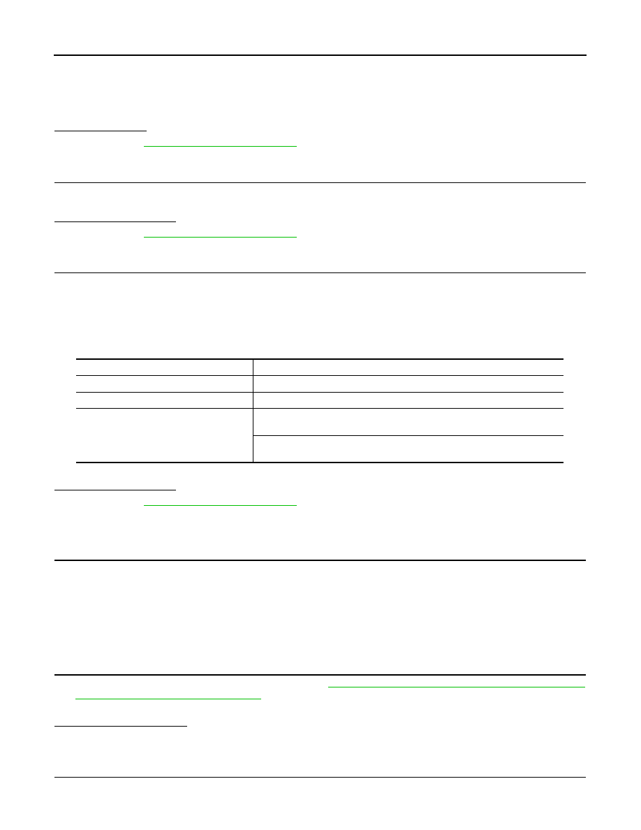
Start engine and drive the vehicle under similar conditions to (1st trip) Freeze Frame Data for 10 minutes.
Refer to the table below.
Hold the accelerator pedal as steady as possible.
Similar conditions to (1st trip) Freeze Frame Data mean that the following conditions should be satisfied at
the same time.

3.

Check 1st trip DTC.

Is 1st trip DTC detected?

YES

>> Go to 

EC-233, "Diagnosis Procedure"

.

NO

>> INSPECTION END

TYPE B

1.

PRECONDITIONING

If DTC Confirmation Procedure has been previously conducted, always perform the following before conduct-
ing the next test.
1.

Turn ignition switch OFF and wait at least 10 seconds.

2.

Turn ignition switch ON.

3.

Turn ignition switch OFF and wait at least 10 seconds.

>> GO TO 2.

2.

PERFORM DTC CONFIRMATION PROCEDURE-I

1.

Clear the mixture ratio self-learning value. Refer to 

EC-19, "MIXTURE RATIO SELF-LEARNING VALUE

CLEAR : Special Repair Requirement"

.

2.

Start engine.

Is it difficult to start engine?

YES

>> GO TO 3.

NO

>> GO TO 4.

3.

RESTART ENGINE

If it is difficult to start engine, the fuel injection system has a malfunction, too.

Engine speed

Engine speed in the freeze frame data 

±

 400 rpm

Vehicle speed

Vehicle speed in the freeze frame data 

±

 10 km/h (6 MPH)

Basic fuel schedule

Basic fuel schedule in freeze frame data 

×

 (1 

±

 0.1)

Engine coolant temperature (T) condition

When the freeze frame data shows lower than 70

°

C (158

°

F),

T should be lower than 70

°

C (158

°

F).

When the freeze frame data shows higher than or equal to 70

°

C (158

°

F),

T should be higher than or equal to 70

°

C (158

°

F).

Revision: 2008 October

2009 Murano

P0172, P0175 FUEL INJECTION SYSTEM FUNCTION

EC-233

< COMPONENT DIAGNOSIS >

[VQ35DE]

C

D

E

F

G

H

I

J

K

L

M

A

EC

N

P

O

Crank engine while depressing accelerator pedal.
NOTE:
• When depressing accelerator pedal three-fourths (3/4) or more, the control system does not start the

engine. Do not depress accelerator pedal too much.

Does engine start?

YES

>> Go to 

EC-233, "Diagnosis Procedure"

.

NO

>> Check exhaust and intake air leakage visually.

4.

PERFORM DTC CONFIRMATION PROCEDURE-II

1.

Keep engine idle for at least 5 minutes.

2.

Check 1st trip DTC.

Is 1st trip DTC detected?

YES

>> Go to 

EC-233, "Diagnosis Procedure"

.

NO

>> GO TO 5.

5.

PERFORM DTC CONFIRMATION PROCEDURE-III

1.

Turn ignition switch OFF and wait at least 10 seconds.

2.

Start engine.

3.

Maintain the following conditions for at least 10 consecutive minutes.
Hold the accelerator pedal as steady as possible.

CAUTION:

Always drive vehicle at a safe speed.

4.

Check 1st trip DTC.

Is 1st trip DTC detected?

YES

>> Go to 

EC-233, "Diagnosis Procedure"

.

NO

>> INSPECTION END

Diagnosis Procedure

INFOID:0000000003388018

1.

CHECK EXHAUST GAS LEAKAGE

1.

Start engine and run it at idle.

2.

Listen for an exhaust gas leakage before three way catalyst (manifold).

Is exhaust gas leakage detected?

YES

>> Repair or replace malfunctioning part.

NO

>> GO TO 2.

2.

CHECK FOR INTAKE AIR LEAKAGE

Listen for an intake air leakage after the mass air flow sensor.

Is intake air leakage detected?

YES

>> Repair or replace malfunctioning part.

NO

>> GO TO 3.

3.

CHECK A/F SENSOR 1 INPUT SIGNAL CIRCUIT

1.

Turn ignition switch OFF.

2.

Disconnect corresponding A/F sensor 1 harness connector.

3.

Disconnect ECM harness connector.

VHCL SPEED SE

50 - 120 km/h (31 - 75 mph)

PBIB1216E

Revision: 2008 October

2009 Murano

EC-234

< COMPONENT DIAGNOSIS >

[VQ35DE]

P0172, P0175 FUEL INJECTION SYSTEM FUNCTION

4.

Check the continuity between A/F sensor 1 harness connector and ECM harness connector.

5.

Check the continuity between A/F sensor 1 harness connector and ground, or ECM harness connector
and ground.

6.

Also check harness for short to power.

Is the inspection result normal?

YES

>> GO TO 4.

NO

>> Repair open circuit, short to ground or short to power in harness or connectors.

4.

CHECK FUEL PRESSURE

1.

Release fuel pressure to zero. Refer to 

EC-545, "Inspection"

.

2.

Install fuel pressure gauge kit [SST (J-44321)] and check fuel pressure. Refer to 

EC-545, "Inspection"

.

Is the inspection result normal?

YES

>> GO TO 5.

NO

>> Replace “fuel filter and fuel pump assembly”.

5.

CHECK MASS AIR FLOW SENSOR

With CONSULT-III

1.

Install all removed parts.

2.

Check “MASS AIR FLOW” in “DATA MONITOR” mode with CONSULT-III.
For specification, refer to 

EC-551, "Mass Air Flow Sensor"

.

With GST

1.

Install all removed parts.

2.

Check mass air flow sensor signal in “Service $01” with GST.
For specification, refer to 

EC-551, "Mass Air Flow Sensor"

.

Is the measurement value within the specification?

YES

>> GO TO 6.

NO

>> Check connectors for rusted terminals or loose connections in the mass air flow sensor circuit or

ground. Refer to 

EC-163, "Diagnosis Procedure"

.

DTC

A/F sensor 1

ECM

Continuity

Bank

Connector

Terminal

Connector

Terminal

P0172

1

F27

1

F8

45

Existed

2

49

P0175

2

F64

1

53

2

57

DTC

A/F sensor 1

Ground

Continuity

Bank

Connector

Terminal

P0172

1

F27

1

Ground

Not existed

2

P0175

2

F64

1

2

DTC

ECM

Ground

Continuity

Connector

Terminal

P0172

F8

45

Ground

Not existed

49

P0175

53

57

At idling: Approximately 350 kPa (3.57 kg/cm

2

, 51 psi)

Revision: 2008 October

2009 Murano

P0172, P0175 FUEL INJECTION SYSTEM FUNCTION

EC-235

< COMPONENT DIAGNOSIS >

[VQ35DE]

C

D

E

F

G

H

I

J

K

L

M

A

EC

N

P

O

6.

CHECK FUNCTION OF FUEL INJECTOR

 With CONSULT-III

1.

Start engine.

2.

Perform “POWER BALANCE” in “ACTIVE TEST” mode with CONSULT-III.

3.

Check that each circuit produces a momentary engine speed drop.

With GST

1.

Let engine idle.

2.

Listen to each fuel injector operating sound.

Is the inspection result normal?

YES

>> GO TO 7.

NO

>> Perform trouble diagnosis for FUEL INJECTOR, refer to

EC-444, "Diagnosis Procedure"

.

7.

CHECK FUEL INJECTOR

1.

Remove fuel injector assembly. Refer to 

EM-45, "Removal and Installation"

.

Keep fuel hose and all fuel injectors connected to fuel tube.

2.

Confirm that the engine is cooled down and there are no fire hazards near the vehicle.

3.

Disconnect all fuel injector harness connectors.

4.

Disconnect all ignition coil harness connectors.

5.

Prepare pans or saucers under each fuel injectors.

6.

Crank engine for about 3 seconds.
Check fuel does not drip from fuel injector.

Is the inspection result normal?

YES

>> GO TO 8.

NO

>> Replace the fuel injectors from which fuel is dripping. Always replace O-ring with new one. 

8.

CHECK INTERMITTENT INCIDENT

Refer to 

GI-40, "Intermittent Incident"

.

>> INSPECTION END

PBIB3332E

Revision: 2008 October

2009 Murano

EC-236

< COMPONENT DIAGNOSIS >

[VQ35DE]

P0181 FTT SENSOR

P0181 FTT SENSOR

Description

INFOID:0000000003388019

The fuel tank temperature sensor is used to detect the fuel tempera-
ture inside the fuel tank. The sensor modifies a voltage signal from
the ECM. The modified signal returns to the ECM as the fuel temper-
ature input. The sensor uses a thermistor which is sensitive to the
change in temperature. The electrical resistance of the thermistor
decreases as temperature increases.
<Reference data>

*: These data are reference values and are measured between ECM terminals 95 (Fuel tank temperature sensor) and ground.

DTC Logic

INFOID:0000000003388020

DTC DETECTION LOGIC

DTC CONFIRMATION PROCEDURE

1.

PRECONDITIONING

If DTC Confirmation Procedure has been previously conducted, always perform the following before conduct-
ing the next test.
1.

Turn ignition switch OFF and wait at least 10 seconds.

2.

Turn ignition switch ON.

3.

Turn ignition switch OFF and wait at least 10 seconds.

>> GO TO 2.

2.

PERFORM DTC CONFIRMATION PROCEDURE-I

1.

Turn ignition switch ON and wait at least 10 seconds.

2.

Check 1st trip DTC.

Is 1st trip DTC detected?

YES

>> Go to 

EC-237, "Diagnosis Procedure"

.

NO

>> GO TO 3.

3.

CHECK ENGINE COOLANT TEMPERATURE

With CONSULT-III

1.

Select “COOLAN TEMP/S” in “DATA MONITOR” with CONSULT-III.

2.

Check “COOLAN TEMP/S” value.

With GST

Follow the procedure “With CONSULT-III” above.

Is “COOLAN TEMP/S” less than 60

°

C (140

°

F)?

YES

>> INSPECTION END

NO

>> GO TO 4.

4.

PERFORM DTC CONFIRMATION PROCEDURE-II

Fluid temperature

[

°

C (

°

F)]

Voltage*

(V)

Resistance

(k

)

20 (68)

3.5

2.3 - 2.7

50 (122)

2.2

0.79 - 0.90

SEF012P

DTC No.

Trouble diagnosis name

DTC detecting condition

Possible cause

P0181

Fuel tank temperature 
sensor circuit range/per-
formance

Rationally incorrect voltage from the sensor is 
sent to ECM, compared with the voltage signals 
from engine coolant temperature sensor and in-
take air temperature sensor.

• Harness or connectors

(The sensor circuit is open or shorted)

• Fuel tank temperature sensor

Revision: 2008 October

2009 Murano

P0181 FTT SENSOR

EC-237

< COMPONENT DIAGNOSIS >

[VQ35DE]

C

D

E

F

G

H

I

J

K

L

M

A

EC

N

P

O

With CONSULT-III

1.

Cool engine down until “COOLAN TEMP/S” is less than 60

°

C (140

°

F).

2.

Wait at least 10 seconds.

3.

Check 1st trip DTC.

With GST

Follow the procedure “With CONSULT-III” above.

Is 1st trip DTC detected?

YES

>> Go to 

EC-237, "Diagnosis Procedure"

.

NO

>> INSPECTION END

Diagnosis Procedure

INFOID:0000000003388021

1.

CHECK GROUND CONNECTION

1.

Turn ignition switch OFF.

2.

Check ground connection E38. Refer to Ground Inspection in 

GI-43, "Circuit Inspection"

.

Is the inspection result normal?

YES

>> GO TO 2.

NO

>> Repair or replace ground connection.

2.

CHECK FUEL TANK TEMPERATURE SENSOR POWER SUPPLY CIRCUIT

1.

Turn ignition switch OFF.

2.

Disconnect “fuel level sensor unit and fuel pump” harness connector.

3.

Turn ignition switch ON.

4.

Check the voltage between “fuel level sensor unit and fuel pump” harness connector and ground.

Is the inspection result normal?

YES

>> GO TO 4.

NO

>> GO TO 3.

3.

DETECT MALFUNCTIONING PART

Check the following.
• Harness connectors E104, B4
• Harness for open or short between ECM and “fuel level sensor unit and fuel pump”

>> Repair open circuit, short to ground or short to power in harness or connector.

4.

CHECK FUEL TANK TEMPERATURE SENSOR GROUND CIRCUIT FOR OPEN AND SHORT

1.

Turn ignition switch OFF.

2.

Disconnect ECM harness connector.

3.

Check the continuity between “fuel level sensor unit and fuel pump” harness connector and ECM harness
connector.

4.

Also check harness for short to ground and short to power.

Is the inspection result normal?

YES

>> GO TO 6.

NO

>> GO TO 5.

5.

DETECT MALFUNCTIONING PART

Check the following.

Fuel level sensor unit and fuel pump

Ground

Voltage

Connector

Terminal

B40

4

Ground

Approx. 5 V

Fuel level sensor unit and fuel pump

ECM

Continuity

Connector

Terminal

Connector

Terminal

B40

5

E16

104

Existed

Revision: 2008 October

2009 Murano

EC-238

< COMPONENT DIAGNOSIS >

[VQ35DE]

P0181 FTT SENSOR

• Harness connectors E105, M11
• Harness connectors M77, B11
• Harness for open or short between “fuel level sensor unit and fuel pump” and ECM

>> Repair open circuit, short to ground or short to power in harness or connector.

6.

CHECK FUEL TANK TEMPERATURE SENSOR

Refer to 

EC-238, "Component Inspection"

.

Is the inspection result normal?

YES

>> GO TO 7.

NO

>> Replace “fuel level sensor unit and fuel pump”.

7.

CHECK INTERMITTENT INCIDENT

Refer to 

GI-40, "Intermittent Incident"

.

>> INSPECTION END

Component Inspection

INFOID:0000000003388022

1.

CHECK FUEL TANK TEMPERATURE SENSOR

1.

Turn ignition switch OFF.

2.

Remove fuel level sensor unit.

3.

Check resistance between “fuel level sensor unit and fuel pump”
terminals by heating with hot water as shown in the figure.

Is the inspection result normal?

YES

>> INSPECTION END

NO

>> Replace “fuel level sensor unit and fuel pump”.

Terminals

Condition

Resistance

4 and 5

Temperature [

°

C (

°

F)]

20 (68)

2.3 - 2.7 k

50 (122)

0.79 - 0.90 k

JMBIA0167ZZ

Revision: 2008 October

2009 Murano

P0182, P0183 FTT SENSOR

EC-239

< COMPONENT DIAGNOSIS >

[VQ35DE]

C

D

E

F

G

H

I

J

K

L

M

A

EC

N

P

O

P0182, P0183 FTT SENSOR

Description

INFOID:0000000003591617

The fuel tank temperature sensor is used to detect the fuel tempera-
ture inside the fuel tank. The sensor modifies a voltage signal from
the ECM. The modified signal returns to the ECM as the fuel temper-
ature input. The sensor uses a thermistor which is sensitive to the
change in temperature. The electrical resistance of the thermistor
decreases as temperature increases.
<Reference data>

*: These data are reference values and are measured between ECM terminals 95 (Fuel tank temperature sensor) and ground.

DTC Logic

INFOID:0000000003388024

DTC DETECTION LOGIC

DTC CONFIRMATION PROCEDURE

1.

PRECONDITIONING

If DTC Confirmation Procedure has been previously conducted, always perform the following before conduct-
ing the next test.
1.

Turn ignition switch OFF and wait at least 10 seconds.

2.

Turn ignition switch ON.

3.

Turn ignition switch OFF and wait at least 10 seconds.

>> GO TO 2.

2.

PERFORM DTC CONFIRMATION PROCEDURE

1.

Turn ignition switch ON and wait at least 5 seconds.

2.

Check 1st trip DTC.

Is 1st trip DTC detected?

YES

>> Go to 

EC-239, "Diagnosis Procedure"

.

NO

>> INSPECTION END

Diagnosis Procedure

INFOID:0000000003591618

1.

CHECK GROUND CONNECTION

1.

Turn ignition switch OFF.

2.

Check ground connection E38. Refer to Ground Inspection in 

GI-43, "Circuit Inspection"

.

Is the inspection result normal?

YES

>> GO TO 2.

NO

>> Repair or replace ground connection.

2.

CHECK FUEL TANK TEMPERATURE SENSOR POWER SUPPLY CIRCUIT

1.

Turn ignition switch OFF.

Fluid temperature

[

°

C (

°

F)]

Voltage*

(V)

Resistance

(k

)

20 (68)

3.5

2.3 - 2.7

50 (122)

2.2

0.79 - 0.90

SEF012P

DTC No.

Trouble diagnosis name

DTC detecting condition

Possible cause

P0182

Fuel tank temperature 
sensor circuit low input

An excessively low voltage from the sensor is 
sent to ECM.

• Harness or connectors

(The sensor circuit is open or shorted.)

• Fuel tank temperature sensor

P0183

Fuel tank temperature 
sensor circuit high input

An excessively high voltage from the sensor is 
sent to ECM.

Revision: 2008 October

2009 Murano

EC-240

< COMPONENT DIAGNOSIS >

[VQ35DE]

P0182, P0183 FTT SENSOR

2.

Disconnect “fuel level sensor unit and fuel pump” harness connector.

3.

Turn ignition switch ON.

4.

Check the voltage between “fuel level sensor unit and fuel pump” harness connector and ground.

Is the inspection result normal?

YES

>> GO TO 4.

NO

>> GO TO 3.

3.

DETECT MALFUNCTIONING PART

Check the following.
• Harness connectors E104, B4
• Harness for open or short between ECM and “fuel level sensor unit and fuel pump”

>> Repair open circuit, short to ground or short to power in harness or connector.

4.

CHECK FUEL TANK TEMPERATURE SENSOR GROUND CIRCUIT FOR OPEN AND SHORT

1.

Turn ignition switch OFF.

2.

Disconnect ECM harness connector.

3.

Check the continuity between “fuel level sensor unit and fuel pump” harness connector and ECM harness
connector.

4.

Also check harness for short to ground and short to power.

Is the inspection result normal?

YES

>> GO TO 6.

NO

>> GO TO 5.

5.

DETECT MALFUNCTIONING PART

Check the following.
• Harness connectors E105, M11
• Harness connectors M77, B11
• Harness for open or short between “fuel level sensor unit and fuel pump” and ECM

>> Repair open circuit, short to ground or short to power in harness or connector.

6.

CHECK FUEL TANK TEMPERATURE SENSOR

Refer to 

EC-240, "Component Inspection"

.

Is the inspection result normal?

YES

>> GO TO 7.

NO

>> Replace “fuel level sensor unit and fuel pump”.

7.

CHECK INTERMITTENT INCIDENT

Refer to 

GI-40, "Intermittent Incident"

.

>> INSPECTION END

Component Inspection

INFOID:0000000003591619

1.

CHECK FUEL TANK TEMPERATURE SENSOR

1.

Turn ignition switch OFF.

Fuel level sensor unit and fuel pump

Ground

Voltage

Connector

Terminal

B40

4

Ground

Approx. 5 V

Fuel level sensor unit and fuel pump

ECM

Continuity

Connector

Terminal

Connector

Terminal

B40

5

E16

104

Existed

Revision: 2008 October

2009 Murano

P0182, P0183 FTT SENSOR

EC-241

< COMPONENT DIAGNOSIS >

[VQ35DE]

C

D

E

F

G

H

I

J

K

L

M

A

EC

N

P

O

2.

Remove fuel level sensor unit.

3.

Check resistance between “fuel level sensor unit and fuel pump”
terminals by heating with hot water as shown in the figure.

Is the inspection result normal?

YES

>> INSPECTION END

NO

>> Replace “fuel level sensor unit and fuel pump”.

Terminals

Condition

Resistance

4 and 5

Temperature [

°

C (

°

F)]

20 (68)

2.3 - 2.7 k

50 (122)

0.79 - 0.90 k

JMBIA0167ZZ

Revision: 2008 October

2009 Murano

EC-242

< COMPONENT DIAGNOSIS >

[VQ35DE]

P0196 EOT SENSOR

P0196 EOT SENSOR

Description

INFOID:0000000003544688

The engine oil temperature sensor is used to detect the engine oil
temperature. The sensor modifies a voltage signal from the ECM.
The modified signal returns to the ECM as the engine oil tempera-
ture input. The sensor uses a thermistor which is sensitive to the
change in temperature. The electrical resistance of the thermistor
decreases as temperature increases.

<Reference data>

*: These data are reference values and are measured between ECM terminals 54
(Engine oil temperature sensor) and 52 (Sensor ground).

DTC Logic

INFOID:0000000003544689

DTC DETECTION LOGIC

NOTE:
If DTC P0196 is displayed with P0197 or P0198, first perform the trouble diagnosis for DTC P0197,
P0198. Refer to 

EC-245, "DTC Logic"

.

DTC CONFIRMATION PROCEDURE

1.

PRECONDITIONING

If DTC Confirmation Procedure has been previously conducted, always perform the following before conduct-
ing the next test.
1.

Turn ignition switch OFF and wait at least 10 seconds.

2.

Turn ignition switch ON.

3.

Turn ignition switch OFF and wait at least 10 seconds.

TESTING CONDITION:
Before performing the following procedure, confirm that battery voltage is more than 11 V at idle.

>> GO TO 2.

2.

PERFORM DTC CONFIRMATION PROCEDURE-I

1.

Start engine and warm it up to normal operating temperature.

2.

Turn ignition switch OFF and wait at least 10 seconds.

SEF594K

Engine oil temperature

[

°

C (

°

F)]

Voltage* (V)

Resistance (k

)

–10 (14)

4.4

7.0 - 11.4

20 (68)

3.5

2.1 - 2.9

50 (122)

2.2

0.68 - 1.00

90 (194)

0.9

0.236 - 0.260

110 (230)

0.6

0.143 - 0.153

SEF012P

DTC No.

Trouble diagnosis name

DTC detecting condition

Possible cause

P0196

Engine oil temperature 
sensor range/perfor-
mance

Rationally incorrect voltage from the sensor is 
sent to ECM, compared with the voltage signals 
from engine coolant temperature sensor and in-
take air temperature sensor.

• Harness or connectors

(The sensor circuit is open or shorted)

• Engine oil temperature sensor

Revision: 2008 October

2009 Murano

P0196 EOT SENSOR

EC-243

< COMPONENT DIAGNOSIS >

[VQ35DE]

C

D

E

F

G

H

I

J

K

L

M

A

EC

N

P

O

3.

Turn ignition switch ON.

4.

Turn ignition switch OFF and wait at least 10 seconds.

5.

Start engine and let it idle for 5 minutes and 10 seconds.

6.

Check 1st trip DTC.

Is 1st trip DTC detected?

YES

>>

EC-243, "Diagnosis Procedure"

.

NO

>> GO TO 3.

3.

PERFORM DTC CONFIRMATION PROCEDURE-II

With CONSULT-III

1.

Select “DATA MONITOR” mode with CONSULT-III.

2.

Check that “COOLAN TEMP/S” indicates above 80

°

C (176

°

F).

If it is above 80

°

C (176

°

F), go to the following steps.

If it is below 80

°

C (176

°

F), warm engine up until “COOLAN TEMP/S” indicates more than 80

°

C (176

°

F).

Then perform the following steps.

3.

Turn ignition switch OFF and soak the vehicle in a cool place.

4.

Turn ignition switch ON.
NOTE:
Do not turn ignition switch OFF until step 8.

5.

Select “DATA MONITOR” mode with CONSULT-III.

6.

Check the following.

If they are within the specified range, perform the following steps.
If they are out of the specified range, soak the vehicle to meet the above conditions. Then perform the fol-
lowing steps.
NOTE:
• Do not turn ignition switch OFF.
• If it is supposed to need a long period of time, do not deplete the battery.

7.

Start engine and let it idle for 5 minutes.

8.

Check 1st trip DTC.

With GST

Follow the procedure “With CONSULT-III” above.

Is 1st trip DTC detected?

YES

>>

EC-243, "Diagnosis Procedure"

.

NO

>> INSPECTION END

Diagnosis Procedure

INFOID:0000000003544690

1.

CHECK GROUND CONNECTION

1.

Turn ignition switch OFF.

2.

Check ground connection E38. Refer to Ground Inspection in 

GI-43, "Circuit Inspection"

.

Is the inspection result normal?

YES

>> GO TO 2.

NO

>> Repair or replace ground connection.

2.

CHECK ENGINE OIL TEMPERATURE SENSOR

Refer to 

EC-244, "Component Inspection"

.

Is the inspection result normal?

YES

>> GO TO 3.

NO

>> Replace engine oil temperature sensor.

3.

CHECK INTERMITTENT INCIDENT

Refer to 

GI-40, "Intermittent Incident"

.

COOLAN TEMP/S

Below 40

°

C (104

°

F)

INT/A TEMP SE

Below 40

°

C (104

°

F)

Difference between “COOLAN TEMP/S” and “INT/A TEMP SE”

Within 6

°

C (11

°

F)

Revision: 2008 October

2009 Murano

EC-244

< COMPONENT DIAGNOSIS >

[VQ35DE]

P0196 EOT SENSOR

>> INSPECTION END

Component Inspection

INFOID:0000000003544691

1.

CHECK ENGINE OIL TEMPERATURE SENSOR

1.

Turn ignition switch OFF.

2.

Disconnect engine oil temperature sensor harness connector.

3.

Remove engine oil temperature sensor.

4.

Check resistance between engine oil temperature sensor termi-
nals by heating with hot water as shown in the figure.

Is the inspection result normal?

YES

>> INSPECTION END

NO

>> Replace engine oil temperature sensor.

Terminals

Condition

Resistance

1 and 2

Temperature [

°

C (

°

F)]

20 (68)

2.1 - 2.9 k

50 (122)

0.68 - 1.00 k

90 (194)

0.236 - 0.260 k

JMBIA0080ZZ

Revision: 2008 October

2009 Murano

P0197, P0198 EOT SENSOR

EC-245

< COMPONENT DIAGNOSIS >

[VQ35DE]

C

D

E

F

G

H

I

J

K

L

M

A

EC

N

P

O

P0197, P0198 EOT SENSOR

Description

INFOID:0000000003668898

The engine oil temperature sensor is used to detect the engine oil
temperature. The sensor modifies a voltage signal from the ECM.
The modified signal returns to the ECM as the engine oil tempera-
ture input. The sensor uses a thermistor which is sensitive to the
change in temperature. The electrical resistance of the thermistor
decreases as temperature increases.

<Reference data>

*: These data are reference values and are measured between ECM terminals 54
(Engine oil temperature sensor) and 52 (Sensor ground).

DTC Logic

INFOID:0000000003544693

DTC DETECTION LOGIC

DTC CONFIRMATION PROCEDURE

1.

PRECONDITIONING

If DTC Confirmation Procedure has been previously conducted, always perform the following before conduct-
ing the next test.
1.

Turn ignition switch OFF and wait at least 10 seconds.

2.

Turn ignition switch ON.

3.

Turn ignition switch OFF and wait at least 10 seconds.

>> GO TO 2.

2.

PERFORM DTC CONFIRMATION PROCEDURE

1.

Start engine and wait at least 5 seconds.

2.

Check 1st trip DTC.

Is 1st trip DTC detected?

SEF594K

Engine oil temperature

[

°

C (

°

F)]

Voltage* (V)

Resistance (k

)

–10 (14)

4.4

7.0 - 11.4

20 (68)

3.5

2.1 - 2.9

50 (122)

2.2

0.68 - 1.00

90 (194)

0.9

0.236 - 0.260

110 (230)

0.6

0.143 - 0.153

SEF012P

DTC No.

Trouble Diagnosis 

Name

DTC detecting condition

Possible Cause

P0197

Engine oil tempera-
ture sensor circuit low 
input

An excessively low voltage from the sensor is 
sent to ECM.

• Harness or connectors

(The sensor circuit is open or shorted.)

• Engine oil temperature sensor

P0198

Engine oil tempera-
ture sensor circuit 
high input

An excessively high voltage from the sensor is 
sent to ECM.

Revision: 2008 October

2009 Murano

EC-246

< COMPONENT DIAGNOSIS >

[VQ35DE]

P0197, P0198 EOT SENSOR

YES

>> Go to 

EC-246, "Diagnosis Procedure"

.

NO

>> INSPECTION END

Diagnosis Procedure

INFOID:0000000003544694

1.

CHECK GROUND CONNECTION

1.

Turn ignition switch OFF.

2.

Check ground connection E38. Refer to Ground Inspection in 

GI-43, "Circuit Inspection"

.

Is the inspection result normal?

YES

>> GO TO 2.

NO

>> Repair or replace ground connection.

2.

CHECK EOT SENSOR POWER SUPPLY CIRCUIT

1.

Disconnect engine oil temperature (EOT) sensor harness connector.

2.

Turn ignition switch ON.

3.

Check the voltage between EOT sensor harness connector and ground.

Is the inspection result normal?

YES

>> GO TO 3.

NO

>> Repair open circuit, short to ground or short to power in harness or connectors.

3.

CHECK EOT SENSOR GROUND CIRCUIT FOR OPEN AND SHORT

1.

Turn ignition switch OFF.

2.

Disconnect ECM harness connector.

3.

Check the continuity between EOT sensor harness connector and ECM harness connector.

4.

Also check harness for short to ground and short to power.

Is the inspection result normal?

YES

>> GO TO 4.

NO

>> Repair open circuit, short to ground or short to power in harness or connectors.

4.

CHECK ENGINE OIL TEMPERATURE SENSOR

Refer to 

EC-246, "Component Inspection"

.

Is the inspection result normal?

YES

>> GO TO 5.

NO

>> Replace engine oil temperature sensor.

5.

CHECK INTERMITTENT INCIDENT

Refer to 

GI-40, "Intermittent Incident"

.

>> INSPECTION END

Component Inspection

INFOID:0000000003668899

1.

CHECK ENGINE OIL TEMPERATURE SENSOR

1.

Turn ignition switch OFF.

2.

Disconnect engine oil temperature sensor harness connector.

3.

Remove engine oil temperature sensor.

EOT sensor

Ground

Voltage

Connector

Terminal

F66

1

Ground

Approx. 5 V

EOT sensor

ECM

Continuity

Connector

Terminal

Connector

Terminal

F66

2

F8

52

Existed

Revision: 2008 October

2009 Murano

P0197, P0198 EOT SENSOR

EC-247

< COMPONENT DIAGNOSIS >

[VQ35DE]

C

D

E

F

G

H

I

J

K

L

M

A

EC

N

P

O

4.

Check resistance between engine oil temperature sensor termi-
nals by heating with hot water as shown in the figure.

Is the inspection result normal?

YES

>> INSPECTION END

NO

>> Replace engine oil temperature sensor.

Terminals

Condition

Resistance

1 and 2

Temperature [

°

C (

°

F)]

20 (68)

2.1 - 2.9 k

50 (122)

0.68 - 1.00 k

90 (194)

0.236 - 0.260 k

JMBIA0080ZZ

Revision: 2008 October

2009 Murano


Content      ..     149      150      151      152     ..