содержание .. 802 803 804 805 ..
Nissan Murano. Manual - part 804
HA-52
< REMOVAL AND INSTALLATION >
LIQUID TANK
LIQUID TANK
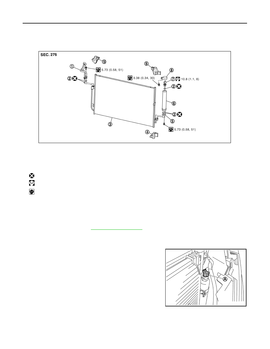
Exploded View
INFOID:0000000009718654
Removal and Installation
INFOID:0000000009718655
REMOVAL
1.
Use refrigerant collecting equipment (for HFC-134a) to discharge the refrigerant.
2.
Remove front grille. Refer to
.
3.
Clean liquid tank and its surrounding area. Then remove dust and rust from liquid tank.
CAUTION:
Be sure to clean carefully.
4.
Disconnect refrigerant pressure sensor connector (A).
1.
Condenser pipe assembly
2.
O-ring
3.
Condenser assembly
4.
Condenser lower bracket LH
5.
Bracket
6.
Liquid tank
7.
Refrigerant pressure sensor
8.
Liquid tank bracket
9.
Condenser upper bracket LH
10. Condenser upper bracket RH
: Always replace after every disassembly.
: N·m (kg-m, ft-lb)
: N·m (kg-m, in-lb)
JPIIA0460GB
JPIIA0543ZZ