содержание .. 800 801 802 803 ..
Nissan Murano. Manual - part 802
HA-44
< REMOVAL AND INSTALLATION >
LOW-PRESSURE PIPE
LOW-PRESSURE PIPE
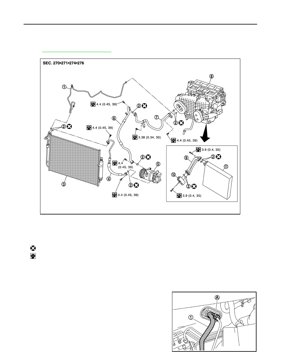
Exploded View
INFOID:0000000009718646
HA-14, "Refrigerant Connection"
.
Removal and Installation
INFOID:0000000009718647
REMOVAL
1.
Use refrigerant collecting equipment (for HFC-134a) to discharge the refrigerant.
2.
Remove mounting bolt (A) and then disconnect low-pressure
pipe (1) from expansion valve.
CAUTION:
Cap or wrap the joint of the A/C piping and expansion valve
with suitable material such as vinyl tape to avoid the entry
of air.
1.
High-pressure pipe
2.
O-ring
3.
Condenser assembly
4.
High-pressure flexible hose
5.
Compressor
6.
Low-pressure flexible hose
7.
Low-pressure pipe
8.
Heater & cooling unit assembly
9.
Evaporator pipe assembly
10. Expansion valve
11.
Evaporator
: Always replace after every disassembly.
: N·m (kg-m, in-lb)
JPIIA1257GB
JPIIA0536ZZ